

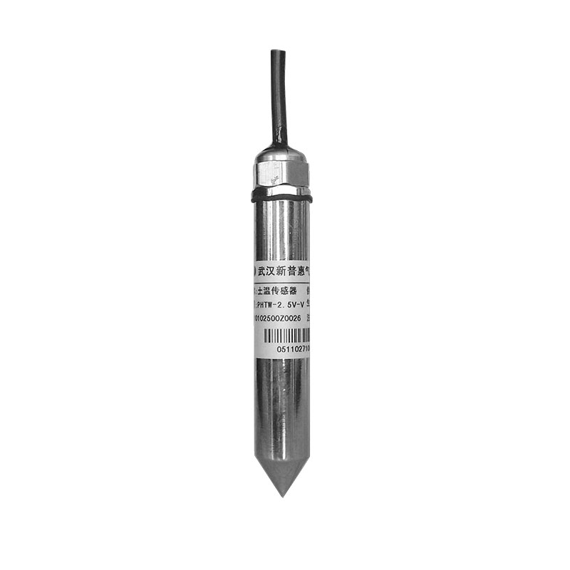
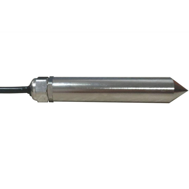
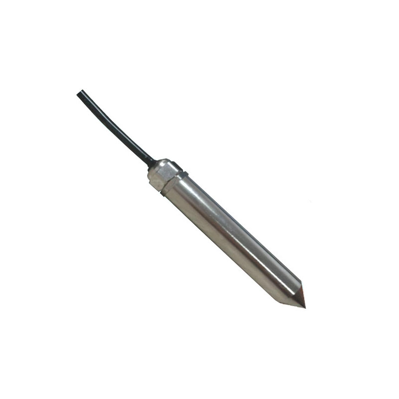
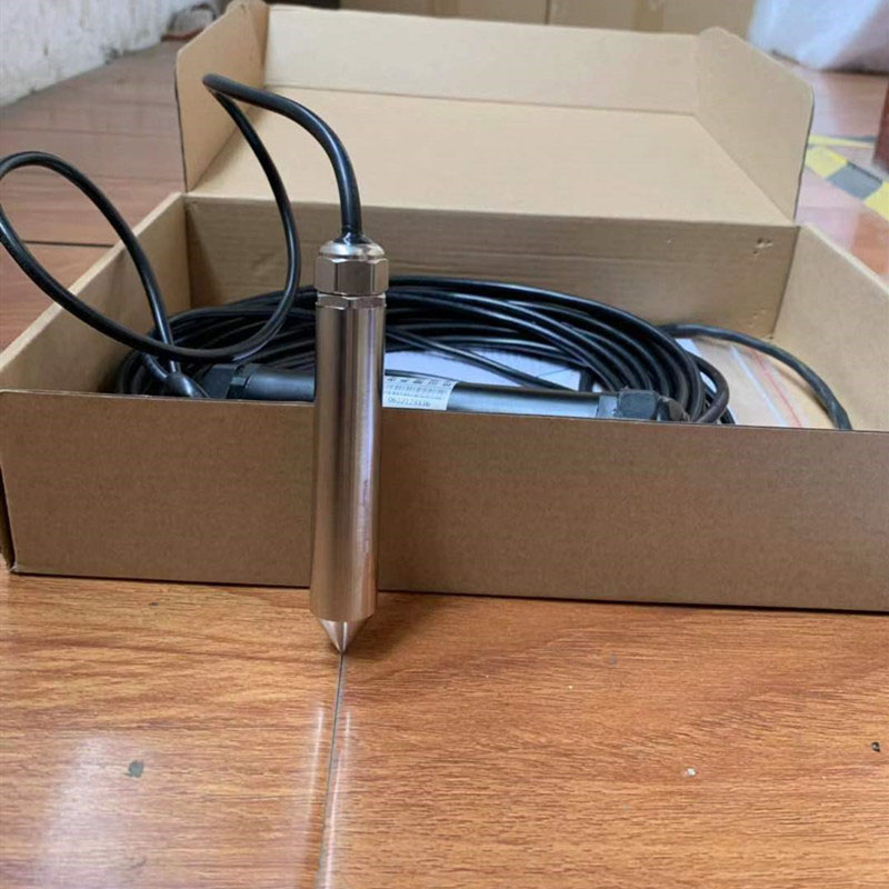
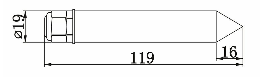
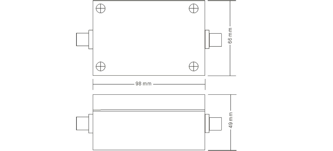
LF-0020 water temperature sensor

| Measurement range | -50~100℃ |
| -20~50℃ | |
| Accuracy | ±0.5℃ |
| Power supply | DC 2.5V |
| DC 5V | |
| DC 12V | |
| DC 24V | |
| Other | |
| Out-put | Current: 4~20mA |
| Voltage: 0~2.5V | |
| Voltage: 0~5V | |
| RS232 | |
| RS485 | |
| TTL Level: (frequency; Pulse width) | |
| Other | |
| Line length | Standard: 10 meters |
| Other | |
| Load capacity | Current output impedance≤300Ω |
| Voltage output impedance≥1KΩ | |
| Operating environment | Temperature: -50℃~80℃ |
| Humidity: ≤100%RH | |
| Produce weight | Probe 145 g, with collector 550 g |
| Power dissipation | 0.5 mW |
Voltage type (0~5V):
T=V / 5 × 70 -20
(T is the measured temperature value (℃), V is the output voltage (V), this formula corresponds to the measurement range -20 ~ 50 ℃)
T=V / 5 × 150 -50
(T is the measured temperature value (℃), V is the output voltage (V), this formula corresponds to the measurement range -50 ~ 100 ℃)
Current type (4~20mA)
T=(I-4)/ 16 × 70 -20
(T is the measurement temperature value (℃), I is the output current (mA), this type corresponds to the measurement range -20 ~ 50 ℃)
T=(I-4)/ 16 × 150 -50
(T is the measured temperature value (℃), I is the output current (mA), this formula corresponds to the measurement range -50 ~ 100 ℃)
Note: The calculation formulas corresponding to different signal outputs and different measurement ranges need to be recalculated!
1. If equipped with a weather station produced by our company, directly connect the sensor to the corresponding interface on the weather station using the sensor cable.
2. If the transmitter is purchased separately, the matching cable sequence of the transmitter is:
|
Line color |
Output signal |
||
|
Voltage type |
Current type |
Communication type |
|
|
Red |
Power+ |
Power+ |
Power+ |
|
Black (green) |
Power ground |
Power ground |
Power ground |
|
Yellow |
Voltage signal |
Current signal |
A+/TX |
|
Blue |
|
|
B-/RX |
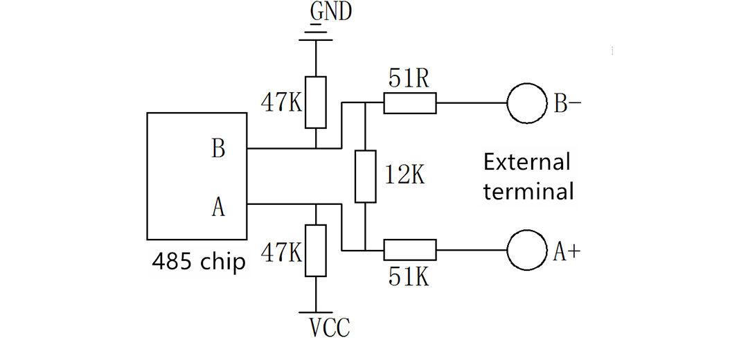
3. Transmitter voltage and current output wiring:
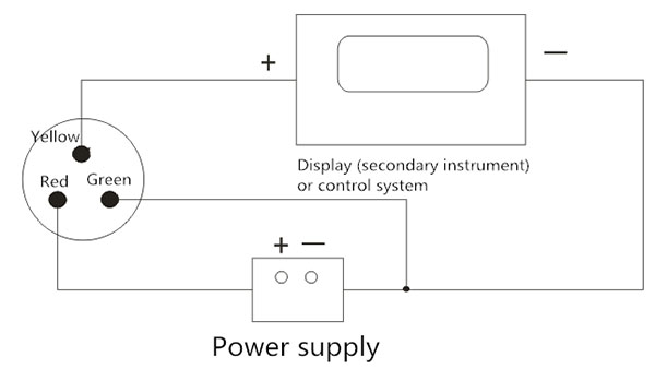
Wiring for voltage output mode
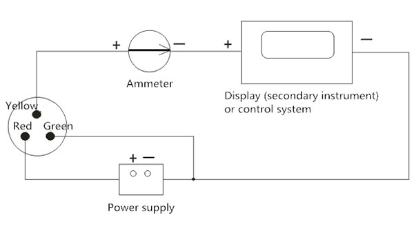
Wiring for current output mode
(Water temperature sensor)
(Water temperature sensor)
1. The serial format
Data bits 8 bits
Stop bit 1 or 2
Check Digit None
Baud rate 9600 Communication interval is at least 1000ms
2. Communication format
[1] Write device address
Send: 00 10 Adress CRC (5 bytes)
Returns: 00 10 CRC (4 bytes)
Note: 1. The address bit of the read and write address command must be 00.
2. Adress is 1 byte and the range is 0-255.
Example: Send 00 10 01 BD C0
Returns 00 10 00 7C
[2] Read device address
Send: 00 20 CRC (4 bytes)
Returns: 00 20 Adress CRC (5 bytes)
Explanation: Adress is 1 byte, the range is 0-255
For example: Send 00 20 00 68
Returns 00 20 01 A9 C0
[3] Read real-time data
Send: Adress 03 00 00 00 02 XX XX
Note: as shown below:
|
Code |
Function definition |
Note |
|
Adress |
Station number (address) |
|
|
03 |
Function code |
|
|
00 00 |
Initial address |
|
|
00 01 |
Read points |
|
|
XX XX |
CRC Check code,front low later high |
Returns: Adress 03 02 XX XX XX XX
|
Code |
Function definition |
Note |
|
Adress |
Station number (address) |
|
|
03 |
Function code |
|
|
02 |
Read unit byte |
|
|
XX XX |
Soil temperature data (high before, low after) |
Hex |
|
XX XX |
Soil humidity data (high before, low after) |
To calculate the CRC code:
1. The preset 16-bit register is FFFF in hexadecimal (that is, all are 1). Call this register the CRC register.
2. XOR the first 8-bit data with the lower bit of the 16-bit CRC register and put the result in the CRC register.
3. Shift the contents of the register to the right by one bit (toward the low bit), fill the highest bit with 0, and check the lowest bit.
4. If the least significant bit is 0: repeat step 3 (shift again), if the least significant bit is 1: the CRC register is XORed with the polynomial A001 (1010 0000 0000 0001).
5. Repeat steps 3 and 4 until 8 times to the right, so that the entire 8-bit data has been processed.
6. Repeat steps 2 to 5 for the next 8-bit data processing.
7. The CRC register finally obtained is the CRC code.
8. When the CRC result is put into the information frame, the high and low bits are exchanged, and the low bit is first.
Connect the sensor according to the instructions in the wiring method, and then insert the sensor probe into the soil to measure the temperature, and supply power to the collector and the sensor to obtain the water temperature at the measurement point.
1. Please check whether the packaging is intact and check whether the product model is consistent with the selection.
2. Do not connect with power on, and then power on after checking the wiring.
3. Do not arbitrarily change the components or wires that have been soldered when the product leaves the factory.
4. The sensor is a precision device. Please do not disassemble it by yourself or touch the surface of the sensor with sharp objects or corrosive liquids in order to avoid damaging the product.
5. Please keep the verification certificate and certificate of conformity, and return it with the product when repairing.
1. When the output is detected, the display indicates that the value is 0 or is out of range. Check whether there is obstruction from foreign objects. The collector may not be able to obtain the information correctly due to wiring problems. Please check whether the wiring is correct and firm.
2. If it is not the above reasons, please contact the manufacturer.
|
Number |
Power supply mode |
Output signal |
Explain |
|
LF-0020 |
|
|
Water temperature sensor |
|
|
5V- |
|
5V powered |
|
12V- |
|
12V powered |
|
|
24V- |
|
24V powered |
|
|
YV- |
|
Other powered |
|
|
|
0 |
No change |
|
|
V |
0-5V |
||
|
V1 |
1-5V |
||
|
V2 |
0-2.5V |
||
|
A1 |
4-20mA |
||
|
A2 |
0-20mA |
||
|
W1 |
RS232 |
||
|
W2 |
RS485 |
||
|
TL |
TTL |
||
|
M |
Pulse |
||
|
X |
Other |
||
|
For example: LF-0020-24V-A1: water temperature sensor (transmitter) 24V power supply, 4-20mA output |
|||
Related products
-

Pressure (Level) Transmitters Liquid Level Sensor
Features ● No pressure hole, no cavity plane structure; ● A variety of signal output forms, voltage, current, frequency signals, etc.; ● High precision, high strength; ● Hygienic, anti-scaling Technical indicators Power supply: 24VDC Output signal: 4~20mA, 0~10mA, 0~20mA, 0~5V, 1~5V, 1~10k...
-
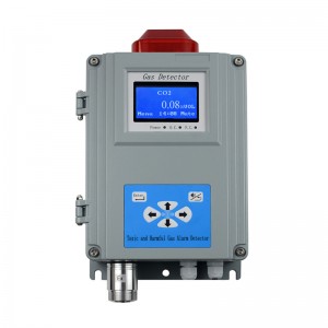
Single-point Wall-mounted Gas Alarm (Carbon dio...
Technical parameter ● Sensor: infrared sensor ● Responding time: ≤40s (conventional type) ● Work pattern: continuous operation, high and low alarm point(could be set) ● Analog interface: 4-20mA signal output [option] ● Digital interface: RS485-bus interface [option] ● Display mode: Graphic LCD ● Alarming mode: Audible alarm -- above 90dB; Light alarm -- High intensity strobes ● Output control: relay o...
-

Ultrasonic Level Difference Meter
Features ● Stable and reliable: We choose high-quality modules from the power supply part in circuit design, and select high-stable and reliable devices for the procurement of key components; ● Patented technology: Ultrasonic intelligent technology software can perform intelligent echo analysis without any debugging and other special steps. This technology has the functions of dynamic thinking and dy...
-
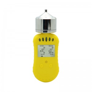
Composite portable gas detector
System Description System configuration 1. Table1 Material List of Composite portable gas detector Portable pump composite gas detector USB Charger Certification Instruction Please check materials immediately after unpacking. The Standard is necessary accessories. The Optional is can be choose according to your needs. If you have no need to calibration, set the alarm parameters, or rea...
-
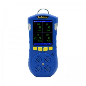
Compound Portable Gas Detector
Product description The composite portable gas detector adopts 2.8-inch TFT color screen display, which can detect up to 4 kinds of gases at the same time. It supports the detection of temperature and humidity. The operation interface is beautiful and elegant; it supports display in both Chinese and English. When the concentration exceeds the limit, the instrument will send out sound, light and vibrat...
-
Clean FCL30 Portable Residual Chlorine Test Ins...
Features 1, 4 keys are simple to operate, comfortable to hold, complete the accurate value measurement with one hand; 2. Backlight screen, display multiple lines, easy to read, automatically shut down without operation; 3. The entire series 1*1.5V AAA battery, easy to replace the battery and electrode; 4. Ship -shaped floating water design, IP67 waterproof level; 5. You can perform throwing water qua...


