

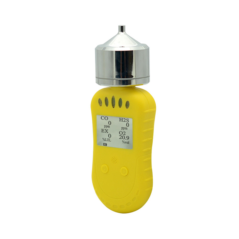
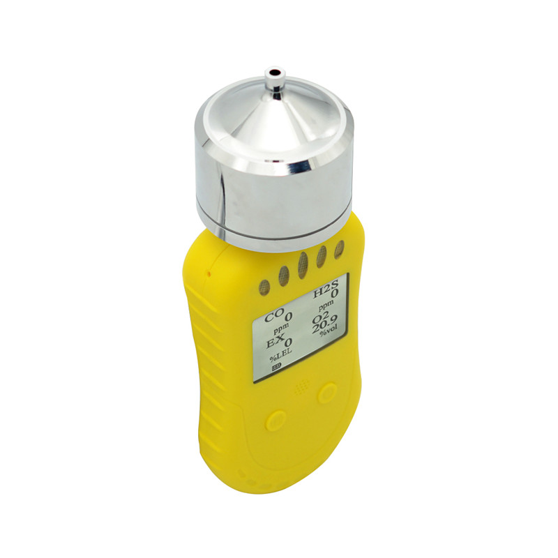
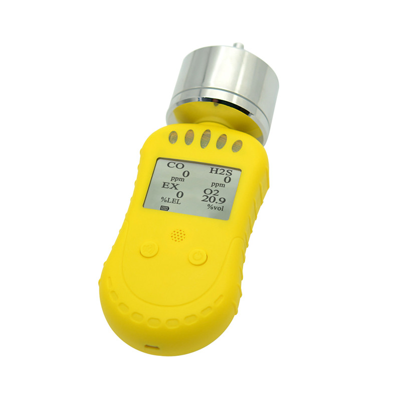
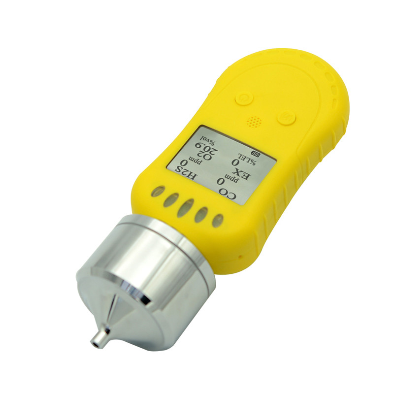
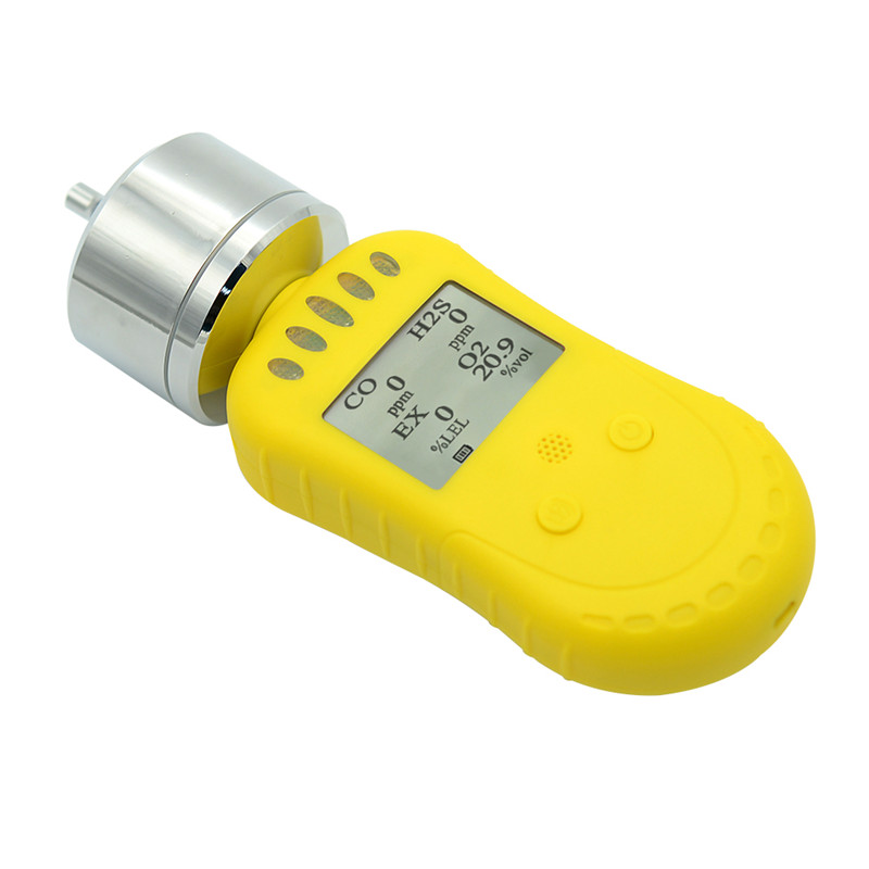
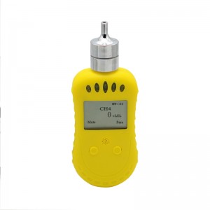
Composite portable gas detector


System configuration
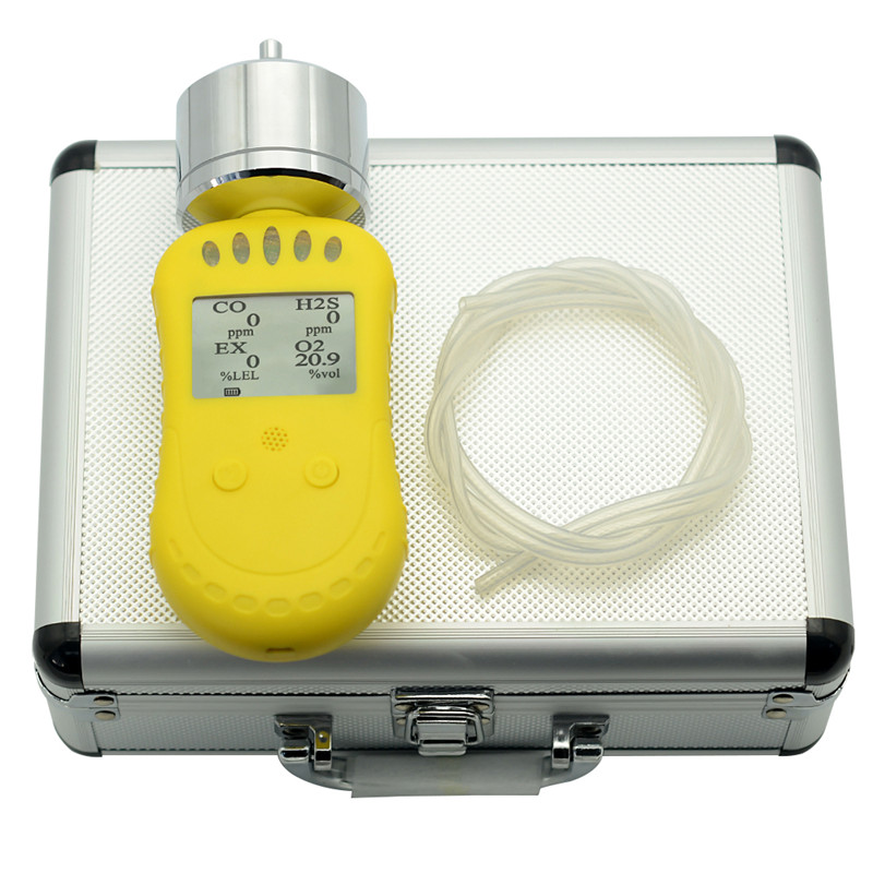
1. Table1 Material List of Composite portable gas detector
 |
 |
| Portable pump composite gas detector | USB Charger |
 |
 |
| Certification | Instruction |
Please check materials immediately after unpacking. The Standard is necessary accessories. The Optional is can be choose according to your needs. If you have no need to calibration, set the alarm parameters, or read the alarm record, don’t purchase the optional accessories.
System parameter
Charging Time: about 3 hours~6 hours
Charging Voltage: DC5V
Service Time: about 15 hours when close pump, (except alarm time)
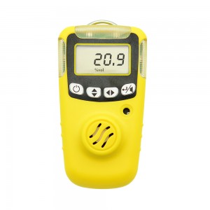
Gas: oxygen, combustible gas, carbon monoxide, hydrogen sulfide. Others gas can be customized based on requirements.
Working Environment: Temperature -20 ~ 50℃; relative humidity <95%(no condensation)
Response Time: Oxygen <30S; carbon monoxide <40s; combustible gas <20S; hydrogen sulfide <40S (others omitted)
Instrument Size: L * W * D; 195(L) * 70(W) *64(D)mm
Measurement Ranges are in the following table 2
|
Gas |
Gas name |
Technical index |
||
|
Measurement range |
Resolution |
Alarm point |
||
|
CO |
Carbon monoxide |
0-2000pm |
1ppm |
50ppm |
|
H2S |
Hydrogen sulfide |
0-100ppm |
1ppm |
10ppm |
|
EX |
Combustible gas |
0-100%LEL |
1%LEL |
25%LEL |
|
O2 |
Oxygen |
0-30%vol |
0.1%vol |
Low 18%vol High 23%vol |
|
H2 |
Hydrogen |
0-1000pm |
1ppm |
35ppm |
|
CL2 |
Chlorine |
0-20ppm |
1ppm |
2ppm |
|
NO |
Nitric oxide |
0-250pm |
1ppm |
35ppm |
|
SO2 |
Sulfur dioxide |
0-20ppm |
1ppm |
5ppm |
|
O3 |
Ozone |
0-50ppm |
1ppm |
2ppm |
|
NO2 |
Nitrogen dioxide |
0-20ppm |
1ppm |
5ppm |
|
NH3 |
Ammonia |
0-200ppm |
1ppm |
35ppm |
Product features
● English display interface
● Pump sampling model
● Flexible customize different gas sensors
● Small and easy to carry
● Two buttons, simple operation
● Miniature vacuum pump, low noise, long life, stable airflow, suction speed 10 adjustable
● With real-time clock can be set as required
● LCD real-time display of gas concentration and alarm status
● Large capacity rechargeable lithium battery
● With vibration, flashing lights and sounds three kinds of alarms, the alarm can be manually silencer
● Simple automatically reset correction
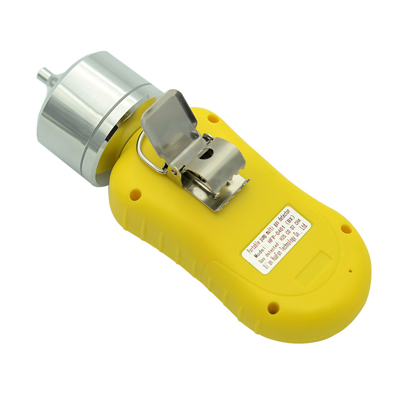
● Strong high-grade alligator clip, easy to carry when operation
● High strength special engineering plastics shell, strong and durable
● Save more than 3,000 alarm records, view by button, connect with computer to analyze or transmit the data(Option).
The detector can simultaneously display four kinds of gases or one kind of numerical indicators of the gas. The index of gas to be detected exceeds or falls below the set standard, the instrument will automatically conduct a series of alarm action, flashing lights, vibration and sound.
The detector has two buttons, a LCD display associated an alarm devices (an alarm light, a buzzer and vibration), and a micro USB interface can be charged by a micro USB; additionally, you can connect the serial extension cable through an adapter plug (TTL to USB)to communicate with a computer, calibration, set the alarm parameters and read alarm history. The detector has real-time storage to record real-time alarm status and time. Specific instructions please refer to the following description.
2.1 Button function
The instrument has two buttons, function as shown in table 3:
Table 3 function
|
Button |
Function |
|
|
Boot, shutdown, please press the button above 3S View parameters, please click  Enter the selected function |
 |
Silence lEnter the menu and confirm the set value, at the same time, please press the button and button.The menu selection button, press thebutton to enter the function |
Note: other Functions in the bottom of the screen as display instrument.
Display
It will go to the boot display by long press the right key in the case of normal gas indicators, shown in FIG.1:
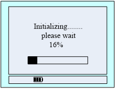
Figure 1 Boot display
This interface is to wait for the instrument parameters stable. The scroll bar indicates the waiting time, about 50s. X% is the current schedule. The lower left corner is the current time of the device which can be set in menu. The power icon below indicates the current battery power (the three grids in the battery icon switch back and forth when charging).
When the percentage turns into 100%, the instrument enters the monitor 4 gas display. Show: gas type, gas concentration, unit, status. Show in FIG. 2.
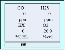
FIG.2 monitors 4 gas displays
If the user purchased a triad with a gas display position displayed as unturned, the two-in-one only shows two gases.
If there is a need to detect a gas display interface can press the right button to switch. The following two kinds of display interface to do a simple introduction.
1. Four kinds of gases display interface:
Show: gas type, gas concentration, unit, status,same as FIG. 2.
Display indicates the pump is open, not display indicates the pump is closed.
When gas has exceeded the target, alarm type(carbon monoxide, hydrogen sulfide, combustible gas alarm type is one or two, while the oxygen alarm type for the upper or lower limit) will display in front of the unit, the backlight lights, LED flashing and with vibration, the speaker icon  disappears slash, shown in FIG.3.
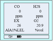
FIG.3 Alarm Interface
Press the Silence icon , the alarm sound disappear (it turns into when alarm).
2. One kind of gas display interface:
In the four gas detection interfaces, press the power-on button to enter a single gas display interface.
Show: gas type, alarm status, time, first lever alarm value (upper limit alarm), second level alarm value (lower limit alarm), range, current gas concentration value, unit.
Below the current concentration values is a "next" "return" character, which represents the corresponding function keys underneath. Press the "next" button below (left click), the display screen shows another gas indicator, and press left four gas interface will display cycle.Finally, the key description is shown in FIG 8.
FIG 4 to FIG 7 are the parameters of four gases. When pressing the button under "return" (right click), the display interface switches to the 4 kinds of gases display interface.
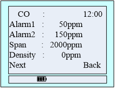
FIG.4 Carbon monoxide
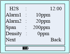
FIG.5 Hydrogen sulfide
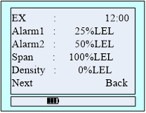
FIG.6 Combustible gas
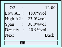
FIG. 7 Oxygen
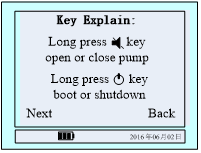
FIG.8 Button Instruction
Single alarm display panel shown in Figure 9, 10:
When one of the gas alarms, the "next" becomes "MUTE", press the blow button to be mute, mute switch to the original font after the "next."
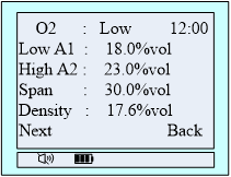
FIG.9 Oxygen alarm status
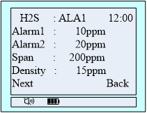
FIG.10 Hydrogen sulfide alarm status
2.3 Menu Description
When the user needs to set parameters, it is necessary to press and hold the left button to enter without releasing it.
Menu interface shown in FIG. 11:

FIG.11 main menu
The icon ➢ refers to the current selected function, press the left select other functions, and press the right key to enter the function.
Function description:
● Set time: set the time, pump speed and air pump switch
● Shut down: close the instrument
● Alarm store: View the alarm record
● Set alarm data: Set the alarm value, low alarm value and high alarm value
● Equipment calibration: Zero correction and calibration equipment
● Back: back to detect four kinds of gases display.
2.3.1 Set time
Under the main menu interface, press the left button to select system Settings, press the right button to enter the system Settings list, press the left button to select time Settings, and press the right button to enter the time Settings interface, as shown in FIG 12
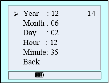
FIG.12 time setting menu
The icon ➢ refers the time to adjust, press right button to select the function, shown in FIG. 13, then press the left button down to change the data. Press the Left key to select another time adjustment function.
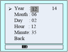
FIG.13 Regulation time
Function Description:
● Year: setting range 17 to 25.
● Month: setting range 01 to 12.
● Day: setting range is from 01 to 31.
● Hour: setting range 00 to 23.
● Minute: setting range 00 to 59.
● Back to return to the main menu.
2.3.2 Set pump speed
In the list of system Settings, left-click to select the pump speed setting and press the right button to enter the pump speed setting interface, as shown in FIG 14:
Press the left button to select the air pump speed, press the right button to return the last menu.
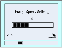
FIG 14: Pump speed setting
2.3.3 Set air pump switch
In the system Settings list, left-click to select the air pump switch, and press the right button to enter the air pump switch Settings interface, as shown in FIG 15:
Press the right button to open or close the pump, press the left button to select return, press the right button to return the last menu.
Switch pump can also be displayed in the concentration interface, long press the left button for more than 3 seconds.
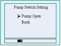
FIG 15: Air pump switch setting
2.3.4 Alarm store
In the main menu, select 'record' function on the left, then right click to enter the recording menu, as shown in figure 16.
● Save Num: total number of storage equipment storage alarm record.
● Fold Num: the amount of data storage equipment if it is larger than the memory total will start back from the first data coverage, the coverage of the times said.
● Now Num: current data storage number, shown has been saved to No. 326.
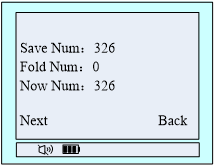
FIG: 16 alarm records check
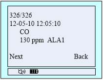
FIG17: specific record query interface
To display the latest record, check a record on the left, click the right button to return to the main menu, as shown in figure 17.
2.3.5 Set alarm data
In the main menu, press the left button to select the 'Set alarm data' function, then press the right button to enter the alarm set gas selection interface, as shown in figure 18. Press the left button to select the type of gas to set the alarm value, right click to enter into the choice of gas alarm value interface. Here in the case of carbon monoxide.
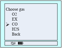
FIG. 18 Choose gas
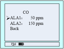
FIG. 19 Alarm data setting
In Figure 19 the interface, press the left button to select the 'level' carbon monoxide alarm value setting, and then press the right button to enter the settings menu, as shown in Figure 20, then press the left button to switch the data, click the right button flashing through the numerical value plus one, about key settings required, after setting up hold down the left button and press the right button, enter the alarm value to confirm the numerical interface, then press the left button, set up after the success of the middle position of the bottom of the screen display, tips 'success' or' fail', as shown in figure 21.
Note: set the alarm value must be less than the default value (lower limit of oxygen must be greater than the default value), otherwise it will fail.
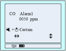
FIG.20 alarm value confirmation
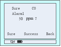
FIG.21 Set successfully
2.3.6 Equipment Calibration
Note:
1.The device is turned on only after the initialization of zero calibration and calibration of gas, when the device is correcting, the correction must be zero, then calibration of the ventilation.
2.Oxygen at standard atmospheric pressure can enter the "gas calibration" menu, correction value is 20.9%vol, must not be carried out in the air "zero correction" operation.
As the same time setting,hold down the left button and press the right button to go to the main menu
Zero calibration
Step1: The position of 'System Settings' menu that indicated by the arrow key is to select the function. Press left key to select ' equipment calibration ' feature items. Then right key to enter the password input calibration menu, shown in Figure 22.According to the last row of icons indicate the interface, left key to switch data bits, right key to plus a flashing digit at the current value. Enter the password 111111 through the coordinate of the two keys. Then hold down the left key, right key, the interface switches to the calibration selection interface, as shown in Figure 23.
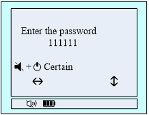
FIG.22 Password Enter
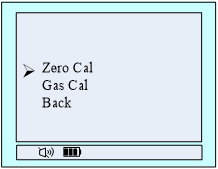
FIG.23 Calibration choice
Step2: Press the left button to select 'zero cal' feature items, then press the right menu to enter the zero point calibration, choose gas shown in Figure 24, after determining the current gas is 0ppm, press the left button to confirm, after the calibration of is successful, the bottom line in the middle will show 'calibration of success' on the contrary displayed as shown in 'calibration of Failed', shown in Figure 25.
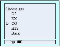
FIG.24 Choose gas
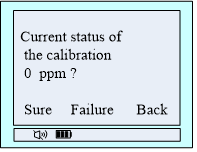
FIG.25 Calibration choice
Step3: After zero calibration is complete, press the right to return to the calibration of selection screen, at this time you can choose gas calibration, press the menu one level exit detection interface, there may also be in the countdown screen, do not press any key when time is reduced to 0 automatically exit the menu, Back to the gas detector interface.
Gas calibration
Step1: After the gas to be stable display value, enter the main menu, call up the Calibration menu selection。The specific methods of operation like the step one of cleared calibration.
Step 2: Select 'gas calibration' feature items, press the right key to enter Calibration value interface, The method of gas selection is the same as that of zero clearing calibration. After selecting the gas type to be calibrated, press the right button to enter the interface of setting the calibration value of the selected gas.As shown in Figure 26.
Then set the concentration of standard gas through the left and right button, suppose now that Calibration is carbon monoxide gas, the concentration of Calibration gas concentration is 500ppm,at this time set to '0500 'can be. As shown in Figure 27.

FIG26 Calibration gas type selection
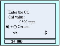
FIG27 Set the concentration of standard gas
Step3: After setting the gas concentration,holding down the left button and press the right button, change the interface to the gas calibration interface, as shown in Figure 28,this interface has a current value detected gas concentration.When the countdown goes to 10, you can press left button to manual calibration, after the 10S, the gas automatic calibrates, after the Calibration is successful, the interface displays' Success! 'On the contrary show' Failed! '.The display format shown in Figure 29.
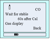
Figure 28 Calibration Interface

Figure 29 Calibration results
Step4: After Calibration is successful, the value of the gas if the display is not stable, You can select 'reset', if the calibration fails, check the calibration gas concentration and calibration settings are the same or not. After calibration of the gas is complete, press the right to return to the gas detection interface.
Step5: After all gas calibration is completed, press the menu to return to the gas detection interface level by level or automatically exit (do not press any button untill the countdown to zero).
2.3.7 Turn off
In the menu list, press the left button to select 'shutdown', press the right button to determine shutdown. Can also be displayed in the concentration interface, long press the right button for more than 3 seconds shutdown.
2.3.8 Return
Under the main menu interface, press the left button to select the 'return' function item, then press the right button to return to the last menu
2.4 Battery Charging and Maintenance
The real-time battery level displays on the display, as shown in the figure below.
 Normal
  Normal
  Low battery
If prompted battery is low, please charge.
Charging method is as follows:
Using dedicated charger, make USB end into the charging port, and then the charger into 220V outlet. Charging time is about 3 to 6 hours.
2.5 Common Problems and Solutions
Table 4 problems and solutions
|
Failure phenomenon |
Cause of the malfunction |
Treatment |
|
Unbootable |
Low battery |
Please charge |
|
crash |
Please contact your dealer or manufacturer for repair |
|
|
Circuit fault |
Please contact your dealer or manufacturer for repair |
|
|
No response on the detection of gas |
Circuit fault |
Please contact your dealer or manufacturer for repair |
|
Display is not accurate |
Sensors expired |
Please contact your dealer or manufacturer to replace the sensor |
|
Long time not calibrated |
Please Calibration |
|
|
Time display error |
The battery is completely depleted |
Timely charge and reset the time |
|
Strong electromagnetic interference |
Reset time |
|
|
Zero calibration feature is unavailable |
Excessive sensor drift |
Timely calibration or replacement of sensors |
1) Be sure to avoid a long-time charging. The charging time may extends, and the instrument's sensor may be affected by differences in the charger (or charging environmental differences) when the instrument is open. In most severe cases, it may even appear instrument error display or alarm situation.
2) The normal charging time of 3 to 6 hours or so, try not to charge the instrument in six hours or more to protect the effective life of the battery.
3) The continuous working time of the instrument after full charge is related to the statue of pump switch and alarms. (because pump opening, the flashing, vibration and sound need extra power, When the alarm is always in the state of alarm, the working time is reduced to the original 1/2 to 1/3).
4) Be sure to avoid using the instrument in a corrosive environment
5) Be sure to avoid contact with water instrument.
6) It’s should be unplug the power cable, and charged every 1-2 months, in order to protect the normal battery life when unused for long time.
7) If the instrument freezes or cannot open in the process of use, there is a small hole at the bottom of the back and you can push the needle against it
If the instrument crash or can not be opened, you can unplug the power cord, then plug the power cord to relieve accident crash situation.
8) Make sure the gas indicators are normal when open the instrument.
9) If you need to read the alarm record, its best enter the menu to accurate time before the initialization has not completed to prevent confusion when reading records.
10) Please use the relevant calibration software if needed, because the instrument alone can not be calibrated.
Note: All attachments is optional, which is based on customer needs matching. These optional need extra charge.
| The Optional | |
 |
 or or  |
| USB to serial cable (TTL) | CD or compressed files |
4.1 Serial communication cables
The connection is as following. The gas Detector+ extension cable + computer
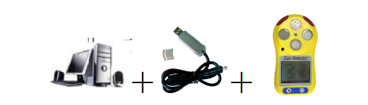
Connection: the USB interface is connected to a computer, the micro USB is connected the Detector.
Please refer to the instructions in CD when operate.
4.2 Setup Parameter
When setting parameters, the USB icon will appear in the display. The location of the USB icon appears according to the display. FIG.30 is one of the plug USB interface when setting parameters:
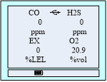
FIG.30 Interface of Set Parameters
The USB icon is flashing when we configure the software in "real time display" and "gas calibration" screen; in the "Parameter Settings" screen, only click the button "read parameters" and "set parameters", the instrument can appeared USB icon.
4.3 View alarm record
The interface is shown below.
After reading the result, the display returns to the four kinds of gases display interface, if you need to stop reading the value of the alarm recording, press the "back" button underneath.

FIG.31 Reading record interface
Declaration: when reading the alarm record, it cannot monitor any gas in real time.
4.4Configuration software section display interface
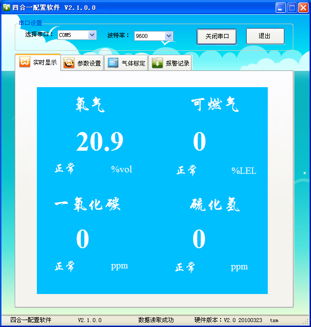
Real-time concentration display
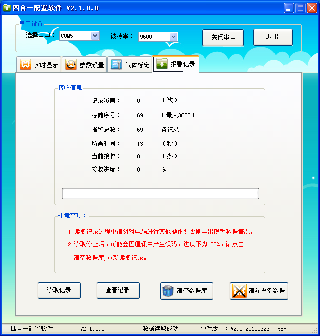
Alarm record reading
Related products
-
Portable pump suction single gas detector
System Description System configuration 1. Table1 Material List of Portable pump suction single gas detector Gas Detector USB Charger Please check materials immediately after unpacking. The Standard is necessary accessories. The Optional can be chosen according to your needs. If you have no need to calibrate, set the alarm parameters, or read the alarm record, don’t purchase the optional acc...
-
Single Gas Detector User’s
Prompt For security reasons, the device only by suitably qualified personnel operation and maintenance. Prior to the operation or maintenance, please read and fully manage all solutions to these instructions. Including operations, maintenance of equipment and process methods. And a very important safety precautions. Read the following Cautions before using the detector. Table 1 Cautions Cautions ...
-
Bus transmitter Instructions
485 Overview 485 is a kind of serial bus which is widely used in industrial communication. 485 communication only needs two wires (line A, line B), long distance transmission is recommended to use shielded twisted pair. Theoretically, the maximum transmission distance of 485 is 4000 feet and the maximum transmission rate is 10Mb/s. The length of the balanced twisted pair is inversely proportional to t...
-
Compound Portable Gas Detector
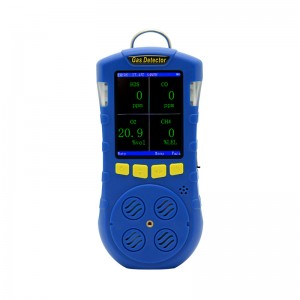
Product description The composite portable gas detector adopts 2.8-inch TFT color screen display, which can detect up to 4 kinds of gases at the same time. It supports the detection of temperature and humidity. The operation interface is beautiful and elegant; it supports display in both Chinese and English. When the concentration exceeds the limit, the instrument will send out sound, light and vibrat...
-

Portable gas sampling pump
Product Parameters ● Display: Large screen dot matrix liquid crystal display ● Resolution: 128*64 ● Language: English and Chinese ● Shell materials: ABS ● Working principle: Diaphragm self-priming ● Flow: 500mL/min ● Pressure: -60kPa ● Noise: <32dB ● working voltage: 3.7V ● Battery capacity: 2500mAh Li battery ● Stand-by time: 30hours(keep pumping open) ● Charging Voltage: DC5V ● Charging Time: 3~5...
-

Composite portable gas detector
System Description System configuration 1. Table1 Material List of Composite portable gas detector Composite portable Gas Detector USB Charger Certification Instruction Please check materials immediately after unpacking. The Standard is necessary accessories. The Optional is can be choose according to your needs. If you have no need to calibration, set the alarm parameters, or read the...


