

Bus transmitter Instructions


485 is a kind of serial bus which is widely used in industrial communication. 485 communication only needs two wires (line A, line B), long distance transmission is recommended to use shielded twisted pair. Theoretically, the maximum transmission distance of 485 is 4000 feet and the maximum transmission rate is 10Mb/s. The length of the balanced twisted pair is inversely proportional to the transmission rate, which is below 100kb/s to reach the maximum transmission distance. The highest rate of transmission can only be achieved over very short distances. Generally, the maximum transmission rate obtained on a twisted pair wire of 100 meters is only 1Mb/s.
For 485 communication products, the transmission distance mainly depends on the transmission line used, usually the better the shielded twisted pair, the farther the transmission distance will be.
There is only one master in the 485 bus, but multiple slave devices are allowed.The master can communicate with any slave, but can not communicate between slaves. The communication distance is subject to 485 standard, which is related to the communication wire material used, communication path environment, communication rate (baud rate) and the number of slaves connected. When the communication distance is far, a 120-ohm terminal resistance is needed to improve the communication quality and stability.The resistance of 120 ohms is usually connected at the start and end.
The connected methods of the bus transmitter and the bus control cabinet is as follows:
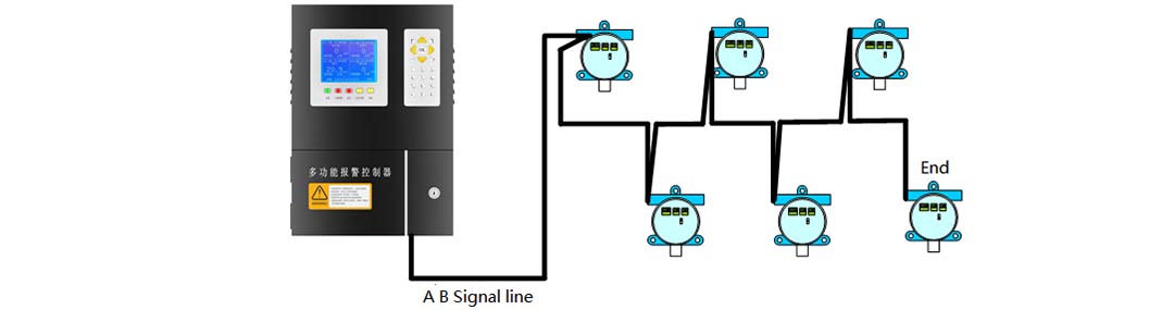
Figure 1: Bus transmitter connection bus control cabinet connection method
Sensor: toxic gas is electrochemical, combustible gas is catalytic combustion, carbon dioxide is infrared
Response time: ≤40s
Working mode: continuous work
Operating voltage: DC24V
Output mode: RS485
Temperature range: -20℃ ~ 50℃
Humidity range: 10 ~ 95% RH [no condensation]
Explosion-proof certificate no. : CE15.1202
Explosion-proof mark: Exd II CT6
Installation: wall-mounted (note: refer to the installation drawing)
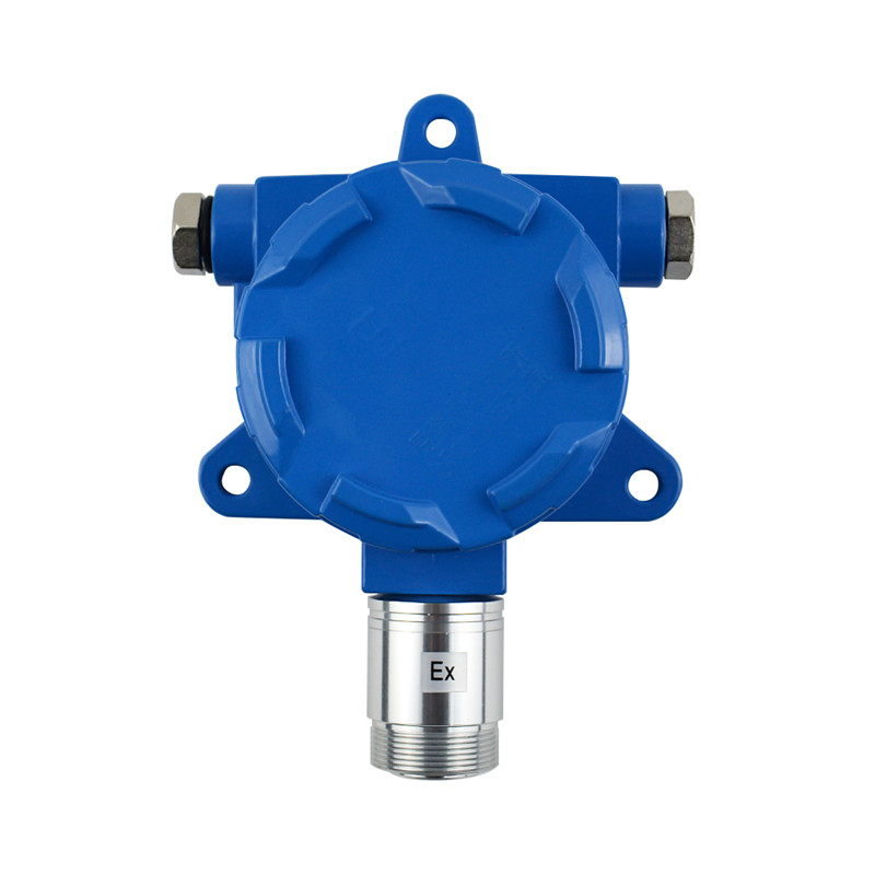
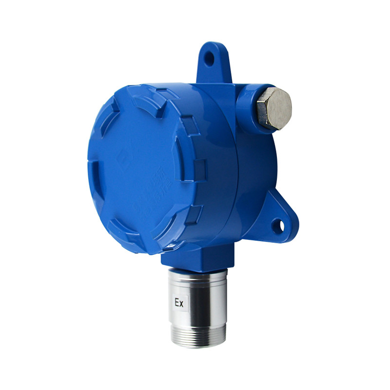
Appearance structure: the transmitter shell adopts the die-cast aluminum shell designed with flameproof structure, the groove design of the upper cover is conducive to locking the shell, the front of the sensor is designed with downward structure to ensure the best contact between the sensor and the gas, and the inlet adopts the explosion-proof waterproof joint.
External dimensions: 150mm×190mm×75mm
Weight:≤1.5kg
Table1:General gas parameter
|
Gas |
Gas name |
Technical index |
||
|
Measurement range |
Resolution |
Alarm point |
||
|
CO |
Carbon monoxide |
0-1000pm |
1ppm |
50ppm |
|
H2S |
Hydrogen sulfide |
0-100ppm |
1ppm |
10ppm |
|
EX |
Combustible gas |
0-100%LEL |
1%LEL |
25%LEL |
|
O2 |
Oxygen |
0-30%vol |
0.1%vol |
Low 18%vol High 23%vol |
|
H2 |
Hydrogen |
0-1000pm |
1ppm |
35ppm |
|
CL2 |
Chlorine |
0-20ppm |
1ppm |
2ppm |
|
NO |
Nitric oxide |
0-250pm |
1ppm |
35ppm |
|
SO2 |
Sulfur dioxide |
0-100ppm |
1ppm |
5ppm |
|
O3 |
Ozone |
0-50ppm |
1ppm |
2ppm |
|
NO2 |
Nitrogen dioxide |
0-20ppm |
1ppm |
5ppm |
|
NH3 |
Ammonia |
0-200ppm |
1ppm |
35ppm |
|
CO2 |
Carbon dioxide |
0-5%vol |
0.01%vol |
0.20%vol |
Note: the above table 1 is only the general gas parameters. Please contact the manufacturer for special gas and range requirements.
Bus transmitter system is a network (gas) monitoring system that integrates gas transmitter and 485 signal transmission and is directly detected and controlled by PC host computer or control cabinet. With a relay output, the relay will close when the gas concentration is in the alarm range. The bus transmitter system is designed in accordance with the design requirements of 485 bus network, and is applied to the standard 485 bus network communication.

Figure 2: Internal diagram of transmitter
The wiring requirement of bus transmitter system is the same as that of standard 485 bus. However, it also integrates some self-generated features, such as:
1. Internal has been integrated with 120 ohm offset resistance, selected by switch.
2. In general, damage to some nodes will not affect the normal operation of the bus transmitter. However, it should be pointed out that if the main components inside a node are seriously damaged, the whole bus transmitter may be paralyzed. And Please contact the manufacturer for specific solutions.
3. System work is relatively stable, support 24 hours of continuous work.
4. The maximum theoretical allowance is 255 nodes.
Note: the signal line does not support hot plug. Recommended use: first connect the 485 bus signal line, then energize the node to work.
Wall-mounted mounting method: draw mounting holes on the wall, use 8mm×100mm expansion bolts, fix expansion bolts on the wall, install the transmitter, and then fix it with nut, elastic pad and flat pad, as shown in figure 3.
After the transmitter is fixed, remove the upper cover and introduce the cable from the inlet. See the structure diagram for the connection terminals with positive and negative polarity (Ex type connection), then lock the waterproof joint, tighten the top cover after checking.
Note: the sensor must be down when installed
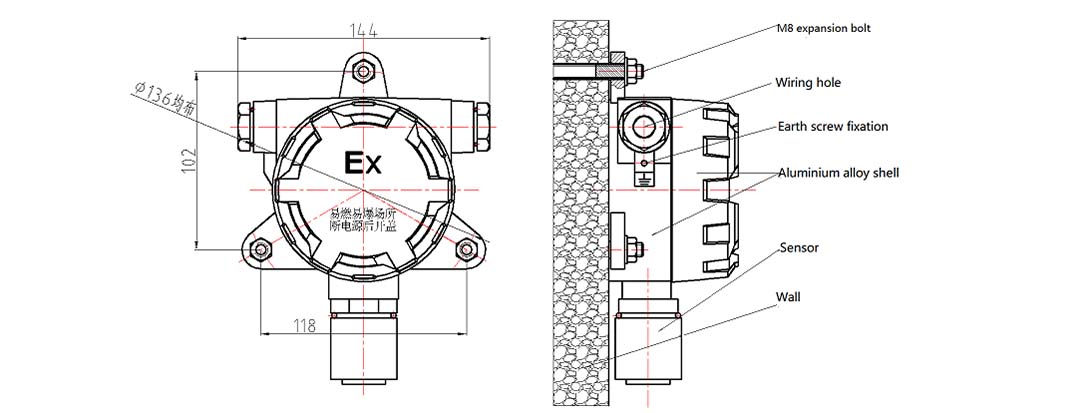
Figure 3:External dimensions and mounting hole bitmap of transmitter
1. Two cables are recommended for the power cord and signal. The power line USES PVVP, and the signal line must adopt the internationally accepted shielded twisted pair (RVSP twisted pair). The use of shielded twisted pair wires helps to reduce and eliminate the distributed capacitance generated between two 485 communication lines and the common-mode interference generated around the communication lines. 485 transmission distance is different according to the selected wire, and generally does not reach the theoretical maximum transmission distance. It is recommended not to use 4 core cable, power and signal using the same cable. Figure 4 is the signal line, and figure 5 is the power line.

Figure 4: Signal Line

Figure 5: Power line
2. Transmission wire in construction to avoid the occurrence of loop, that is, the formation of a multi - loop coil.
3. When the construction should be separate through the tube, as far as possible away from the high voltage wire, to avoid close to strong electricity, strong magnetic field signals.
485 bus to use hand-in-hand structure, resolutely eliminate star connection and bifurcation connection. The star connection and the bifurcated connection will produce the reflection signal, thus affecting the 485 communication. The shield is connected to the transmitter housing. The line diagram is shown in figure 6.
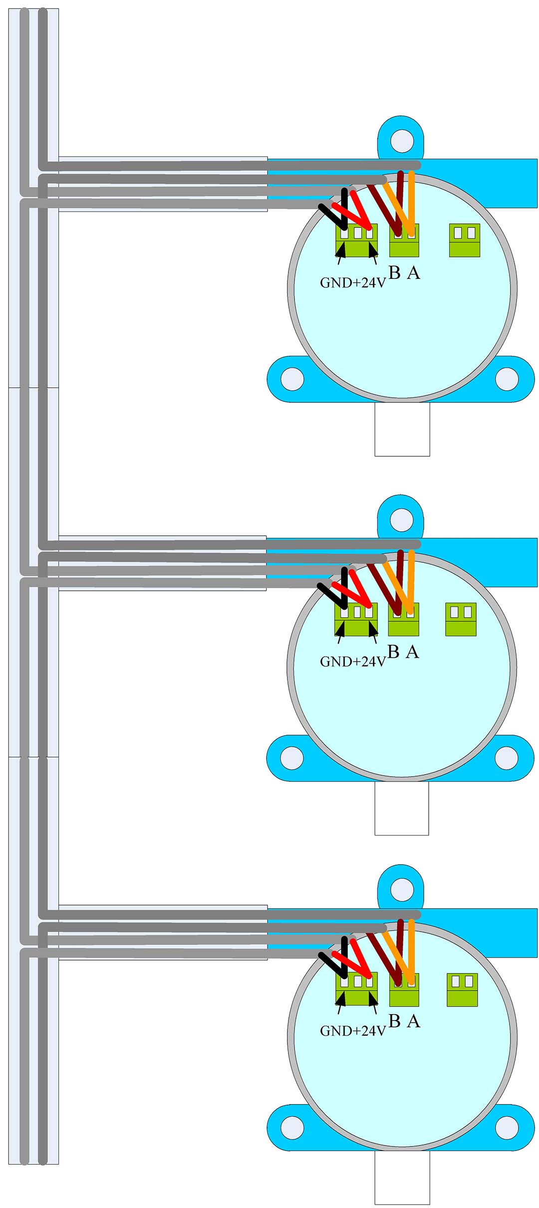
Figure 6: Detailed line chart
The correct wiring diagram is shown in figure 7 and the wrong wiring diagram is shown in figure 8.

Figure 7: Correct wiring diagram

Figure 8: Wrong wiring diagram
If the distance is too long, a repeater is needed, and the repeater connection method is shown in figure 9. Power supply wiring is not shown.

Figure 9:Repeater connection method
4. After wiring is completed, connect parts of the transmitters first, cut off the power cord and signal line, and make end connection at the transmitter, as shown in figure 2. Use a multimeter to test whether there is a short circuit between signals and power lines.The resistance value between signal line A and B is about 50-70 ohms. Please check whether the host can communicate with each transmitters and then connect the rest parts for testing. Set the last transmitter switch currently connected to on,Other transmitter switch set to 1.
Note:the end termination is only for bus wire connection. Other wire connection method is not permitted.
When there are many pieces of transmitters and far distance, please pay attentions to below:
If all nodes fail to receive data, and the indicator light in the transmitter does not work, it indicates that the power supply cannot provide enough current, and another switching power supply is needed, so it is recommended to use a high-power power supply.In the position between the two switching power supply, disconnect 24V+, 24V- connected to avoid interference between two switching power supply.
B.If the node loss is serious, it is because the communication distance is too far, the bus data is not stable, need to use a repeater to extend the communication distance.
5. The bus wire transmitter is with only one normal open passive relay.When the gas concentration exceed preset alarm point the relay get closed, below the alarm point,the relay will disconnect the user shall make wiring according to the requirements. If you want to control the fan or other external equipment, please connect the external equipment and the relay interface in series to the appropriate power supply (as shown in figure 10 the wiring diagram of the relay )

Figure 10 the wiring diagram of the relay
RS485 bus transmitter system related problems and solutions
1. Some terminals have no data: usually the node is not powered on due to some external reason, the way is to check whether the indicator light on the circuit board is flashing.If the indicator light is not on, the node can be recharged separately.
2. The indicator light flashes normally, but there is no data. It is necessary to check whether wires A and B are connected normally and whether connected in reverse.Disconnect the power supply of this node and then plug in the data cable again to see if you can get this node data.Special note: do not connect the power cord to the data cable port, it will seriously damage the RS485 device.
3. Terminal connection is required. If 485 bus wiring is too long (over 100 meters), it is recommended to carry out end connection.The end connection is usually required at the end of RS485, as shown in figure 2.If the bus wiring is too long, the repeater connection can be used to extend the transmission distance.(note: If RS485 repeater is used, there is no need for terminal connection at the repeater and the internal integration is completed.
4. Except for the above problems, if the indicator light flashes normally (1 flash per second) and communication fails, the node can be judged damaged (provided the line communication is normal).If a large number of nodes cannot communicate, please first makes sure the power and communication lines is OK, and then consult relevant technical support.
The warranty period of the gas testing instrument manufactured by our company is 12 months, which starts from the date of delivery.In the process of use, the user should comply with the operating instructions, due to improper use, or working conditions caused the instrument damage, is not covered in the warranty.
Please read the instructions carefully before using the instrument.
The operation of the instrument must follow the rules specified in the instructions.
The maintenance of instruments and the replacement of parts shall be handled by our company or local maintenance stations.
If the user does not follow the above instructions, start up or replace the parts, the reliability of the instrument should be the responsibility of the operator.
The use of the instrument shall also comply with the laws and regulations of the relevant domestic authorities and the instrument management in the factory.
Related products
-
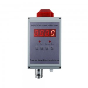
Single-point Wall-mounted Gas Alarm
Structure chart Technical parameter ● Sensor: electrochemistry, catalytic combustion, infrared, PID...... ● Responding time: ≤30s ● Display mode: High brightness red digital tube ● Alarming mode: Audible alarm -- above 90dB(10cm) Light alarm --Φ10 red light-emitting diodes (leds) ...
-
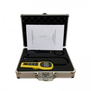
Portable combustible gas leak detector
Product Parameters ● Sensor Type: Catalytic sensor ● Detect gas: CH4/Natural gas/H2/ethyl alcohol ● Measure range: 0-100%lel or 0-10000ppm ● Alarm point: 25%lel or 2000ppm ,adjustable ● Accuracy: ≤5%F.S ● Alarm: Voice + vibration ● Language: Support English& Chinese menu switch ● Display: LCD digital display, Shell Material: ABS ● Working voltage: 3.7V ● Battery capacity: 2500mAh Lithium battery ●...
-
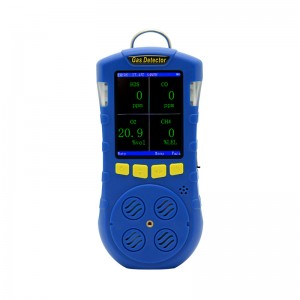
Compound Portable Gas Detector
Product description The composite portable gas detector adopts 2.8-inch TFT color screen display, which can detect up to 4 kinds of gases at the same time. It supports the detection of temperature and humidity. The operation interface is beautiful and elegant; it supports display in both Chinese and English. When the concentration exceeds the limit, the instrument will send out sound, light and vibrat...
-
Composite portable gas detector
System Description System configuration 1. Table1 Material List of Composite portable gas detector Portable pump composite gas detector USB Charger Certification Instruction Please check materials immediately after unpacking. The Standard is necessary accessories. The Optional is can be choose according to your needs. If you have no need to calibration, set the alarm parameters, or rea...
-

Composite portable gas detector
System Description System configuration 1. Table1 Material List of Composite portable gas detector Composite portable Gas Detector USB Charger Certification Instruction Please check materials immediately after unpacking. The Standard is necessary accessories. The Optional is can be choose according to your needs. If you have no need to calibration, set the alarm parameters, or read the...
-

Portable gas sampling pump
Product Parameters ● Display: Large screen dot matrix liquid crystal display ● Resolution: 128*64 ● Language: English and Chinese ● Shell materials: ABS ● Working principle: Diaphragm self-priming ● Flow: 500mL/min ● Pressure: -60kPa ● Noise: <32dB ● working voltage: 3.7V ● Battery capacity: 2500mAh Li battery ● Stand-by time: 30hours(keep pumping open) ● Charging Voltage: DC5V ● Charging Time: 3~5...


