

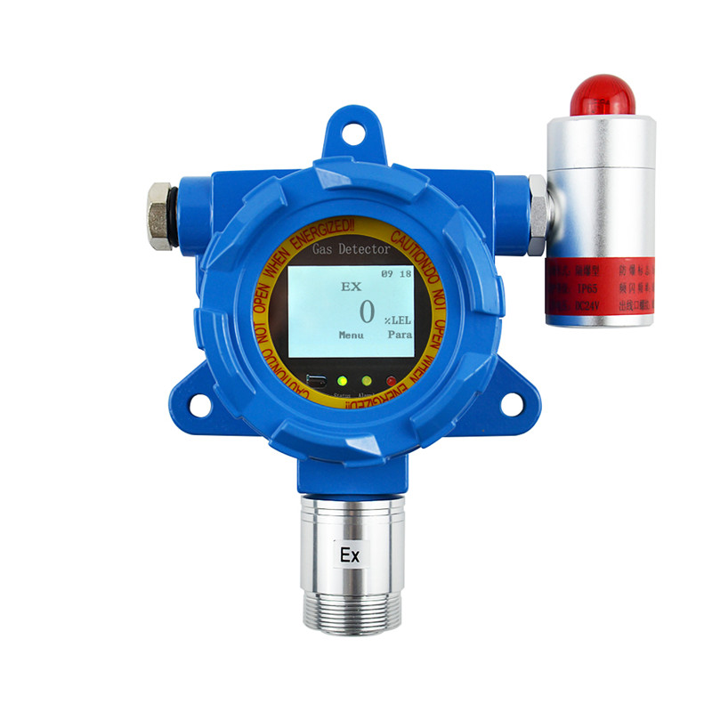
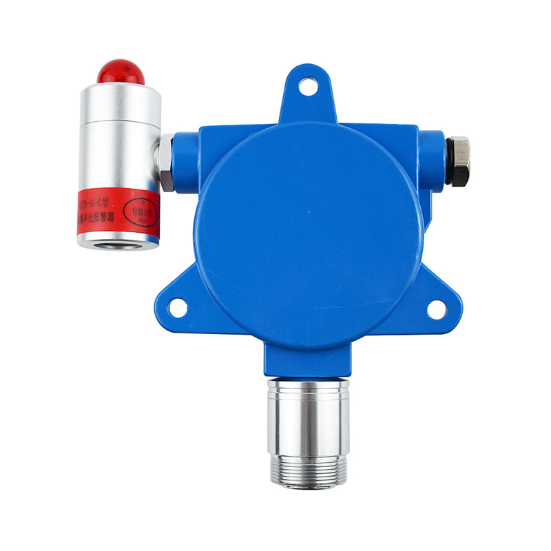
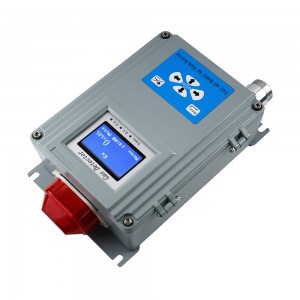
Fixed single gas transmitter LCD display (4-20mA\RS485)


System configuration
Table 1 bill of materials for standard configuration of fixed single gas transmitter
|
Standard configuration |
||
|
Serial number |
Name |
Remarks |
|
1 |
Gas transmitter |
|
|
2 |
Instruction manual |
|
|
3 |
Certificate |
|
|
4 |
Remote control |
|
Please check whether the accessories and materials are complete after unpacking. Standard configuration is a necessary accessory for purchasing equipment.
1.2 System parameter
● Overall dimension: 142mm × 178.5mm × 91mm
● Weight: about 1.35Kg
● Type of sensor: electrochemical type (combustible gas is catalytic combustion type, otherwise specified)
● Detection gases: oxygen (O2), combustible gas (Ex), toxic and harmful gases (O3,CO, H2S, NH3, Cl2, etc.)
● Response time: oxygen ≤ 30s; carbon monoxide ≤ 40s; combustible gas ≤ 20s; (others omitted)
● Working mode: continuous operation
● Working voltage: DC12V ~ 36V
● Output signal: RS485-4-20ma (configured according to customer requirements)
● Display mode: Graphic LCD , English
● Operation mode: key, infrared remote control
● Control signal: 1 group of passive switch output, the maximum load is 250V AC 3a
● Additional functions: time and calendar display, can store 3000 + data records
● Temperature range: - 20 ℃~ 50 ℃
● Humidity range: 15% ~ 90% (RH), non-condensing
● Explosion proof Certificate No.: CE20.1671
● Explosion proof sign: Exd II CT6
● Wiring mode: RS485 is four wire system, 4-20mA is three wire
● Transmission cable: determined by means of communication, see below
● Transmission distance: less than 1000m
● The measurement ranges of common gases are shown in Table 2 below
Table 2 The measurement ranges of common gases
|
Gas |
Gas name |
Technical index |
||
|
Measurement range |
Resolution |
Alarm point |
||
|
CO |
Carbon monoxide |
0-1000pm |
1ppm |
50ppm |
|
H2S |
Hydrogen sulfide |
0-100ppm |
1ppm |
10ppm |
|
EX |
Combustible gas |
0-100%LEL |
1%LEL |
25%LEL |
|
O2 |
Oxygen |
0-30%vol |
0.1%vol |
Low 18%vol High 23%vol |
|
H2 |
Hydrogen |
0-1000pm |
1ppm |
35ppm |
|
CL2 |
Chlorine |
0-20ppm |
1ppm |
2ppm |
|
NO |
Nitric oxide |
0-250pm |
1ppm |
35ppm |
|
SO2 |
Sulfur dioxide |
0-20ppm |
1ppm |
5ppm |
|
O3 |
Ozone |
0-5ppm |
0.01ppm |
1ppm |
|
NO2 |
Nitrogen dioxide |
0-20ppm |
1ppm |
5ppm |
|
NH3 |
Ammonia |
0-200ppm |
1ppm |
35ppm |
Note: the instrument can only detect a specified gas, and the type and range of gas that can be measured shall be subject to the actual product.
The external dimensions of the instrument are shown in Figure 1
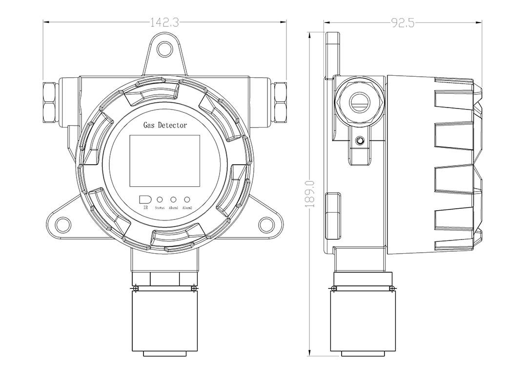
Figure 1 external dimension of the instrument
2.1 Fixed description
Wall mounted type: draw the installation hole on the wall, use 8mm × 100mm expansion bolt, fix the expansion bolt on the wall, install the transmitter, and then fix it with nut, elastic pad and flat pad, as shown in Figure 2.
After the transmitter is fixed, remove the upper cover and lead in the cable from the inlet. Connect the terminal according to the positive and negative polarity (Ex type connection shown in the diagram) as shown in the structural drawing, then lock the waterproof joint, and tighten the upper cover after all links are checked to be correct.
Note: the sensor must be downward during installation.

Figure 2 outline dimension and installation hole diagram of transmitter
2.2 Wiring instructions
2.2.1 RS485 mode
(1) Cables shall be rvvp2 * 1.0 and above, two 2-core wires or rvvp4 * 1.0 and above, and one 4-core wire.
(2) The wiring only supports hand-in-hand method. Figure 3 shows the overall wiring diagram, and Figure 4 shows the detailed internal wiring diagram.
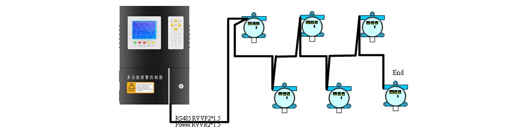
Figure 3 overall wiring diagrams
(1) More than 500m, need to add repeater. In addition, when the transmitter is connected too much, the switching power supply should be added.
(2) It can be connected to bus control cabinet or PLC, DCS, etc. Modbus communication protocol is needed to connect PLC or DCS.
(3) For the terminal transmitter, turn the red toggle switch on the transmitter to the on direction.
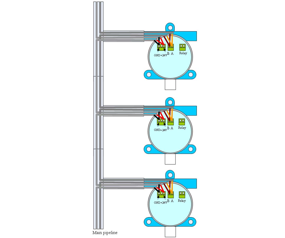
Figure 4 connection of RS485 bus transmitter
2.2.2 4-20mA mode
(1) The cable shall be RVVP3 * 1.0 and above, 3-core wire.

Figure 5 4-20mA connections
The instrument can display at most one gas value index. When the index of the gas to be detected is in the alarm range, the relay will be closed. If the sound and light alarm light is used, the sound and light alarm will be sent out.
The instrument has three sound light interfaces and one LCD switch.
The instrument has the function of real-time storage, which can record the alarm status and time in real time. Please refer to the following instructions for specific operation and function description.
3.1 Key description
The instrument has three buttons, and the functions are shown in Table 3
Table 3 key description
|
Key |
Function |
Remarks |
|
KEY1 |
Menu selection | Left key |
|
KEY2 |
lEnter the menu and confirm the setting value | Middle key |
|
KEY3 |
View parameters Access to the selected function |
Right key |
Note: other functions are subject to the display at the bottom of the instrument screen.
It can also be operated by infrared remote control. The key function of infrared remote control is shown in Figure 6.

Figure 6 remote control key descriptions
3.2 Display interface
After the instrument is powered on, enter the boot display interface. As shown in Figure 7:

Figure 7 boot display interface
This interface is to wait for the instrument parameters to stabilize. The scroll bar in the middle of the LCD indicates the waiting time, about 50s. X% is the progress of the current run. In the lower right corner of the display is the current instrument time (this time can be changed as needed in the menu).
When the waiting time percentage is 100%, the instrument will enter the monitoring gas display interface. Take carbon monoxide as an example, as shown in Figure 8.
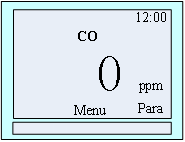
Figure 8 monitoring gas displays
If you need to view the gas parameters, click right key.
1) Detection display interface:
Display: gas type, gas concentration value, unit, state. As shown in Figure 8.
When the gas exceeds the target, the alarm type of the unit will be displayed in the front of the unit (the alarm type of carbon monoxide, hydrogen sulfide and combustible gas is level 1 or level 2, while the alarm type of oxygen is the upper or lower limit), as shown in Figure 9.
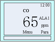
Figure 9 interface with gas alarm
1) Parameter display interface:
In the gas detection interface, right-click to enter the gas parameter display interface.
Display: gas type, alarm state, time, first level alarm value (lower limit alarm), second level alarm value (upper limit alarm), range, current gas concentration value, unit, gas position.
When pressing the key (right key) under "return", the display interface will switch to the detection gas display interface.
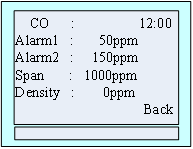
Figure 10 carbon monoxide
3.3 Menu instruction
When the user needs to set parameters, press the middle key.
The main menu interface is shown in Figure 11:
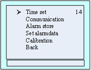
Figure 11 main menu
Icon ➢ refers to the currently selected function. Press the left button to select other functions, and press the right button to enter the function
Functions:
★ Time set: Set time setting
★ Communication settings: Communication baud rate, device address
★ Alarm store: View alarm records
★ Set alarm data: Set the alarm value, the first and second alarm value
★ Calibration: Zero calibration and calibration of instrument
★ Back: Return to the detection gas display interface.
3.3.1 Time setting
In the main menu interface, press the left button to select system Settings, press the right button to enter the system Settings list, press the left button to select time Settings, and press the right button to enter the time setting interface, as shown in Figure 12:
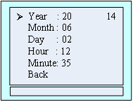
Figure 12 time setting
Icon ➢ refers to the currently selected time to be adjusted. Press the right button to select this function, and the selected number will be displayed as shown in Figure 13. Then press the left button to change the data. Press the left button to adjust other time functions.
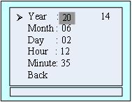
Figure 13 setting Year function
Functions:
★ Year Range from 20~30
★ Month Range from 01~12
★ Day Range from 01~31
★ Hour Range from 00~23
★ Minute Range from 00~59
★ Return Back to the main menu interface
3.3.2 Communication settings
The communication setting menu is shown in Figure 14 to set the parameters related to communication
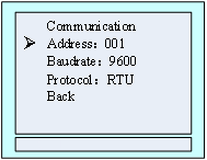
Figure 14 communication settings
Address Setting range: 1~200, the range of addresses occupied by the device is: first address~ (first address + total gas -1)
Baud rate Setting range: 2400, 4800, 9600, 19200. Default: 9600, generally no need to set.
Protocol Read only, non-standard and RTU, non-standard is to connect our company's bus control cabinet etc. RTU is to connect PLC, DCS etc.
As shown in Figure 15, set the address, press the left button to select the setting bit, press the right button to change the value, press the middle button to confirm, the reconfirmation interface appears, click the left button to confirm.
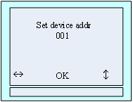
Figure 15 setting the address
As shown in Figure 16, select the desired Baud rate, press the right button to confirm, and the interface for reconfirmation appears. Click the left button to confirm.
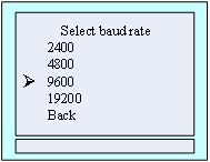
Figure 16 Select Baud rate
3.3.3 Record storage
In the main menu interface, press the left button to select the "record storage" function item, then press the right button to enter the record storage menu, as shown in Figure 17.
Total storage: the total number of alarm records that the instrument can store.
Number of overwrites: If the amount of data stored in the device is greater than the total number of storage, it will be overwritten starting from the first piece of data.
Current serial number: the number of the currently saved data. Figure 20 shows that it has been saved to No. 326.
First display the latest record, press the left button to view the next record, as shown in Figure18, and press the right button to return to the main menu

Figure 17 number of stored records
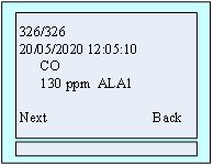
Figure 18 Record details
3.3.4 Alarm setting
Under the main menu interface, press the left button to select the "Alarm Setting" function, and then press the right button to enter the alarm setting gas selection interface, as shown in Figure 22. Press the left button to select the gas type to set the alarm value, and press the right button to enter the selected gas alarm value interface. Let's take carbon monoxide.

Figure 19 select alarm setting gas
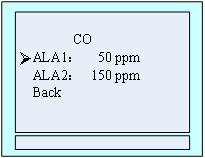
Figure 20 carbon monoxide alarm value setting
In figure 23 interface, press left key to select carbon monoxide "level I" alarm value, then right click to enter the Settings menu, as shown in figure 24, at this time press the left button switch data bits, right click flicker value plus one, through the left and right buttons to set the required value, set up is completed, press the middle button to enter the alarm value confirmed numerical interface, press left key to confirm at this time, if the setting is success, will display "setting success" in the middle of the rows at the lowest position, otherwise tip "setting failure", as shown in figure 25.
Note: The alarm value set must be less than the factory value (the lower oxygen limit must be greater than the factory value), otherwise the setting will fail.
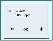
Figure 21 setting alarm value
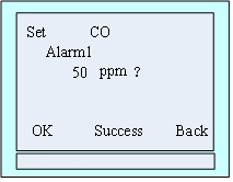
Figure 22 successful setting interface
3.3.5 Calibration
Note: 1. Zero correction can be made after starting the instrument and finishing the initialization.
2. Oxygen can enter the "Gas Calibration" menu under standard atmospheric pressure. The calibration display value is 20.9%vol. Do not perform zero correction operations in the air.
Zero correction
Step 1: In the main menu interface, press the left button to select the "Device Calibration" function, and then press the right button to enter the menu of input calibration password, as shown in Figure 23. According to the icon in the last line of the interface, press the left button to switch data bit, press the right button to add 1 to the current flashing bit value, enter the password 111111 through the combination of these two buttons, and then press the middle button to switch to the calibration and selection interface, as shown in Figure 24.
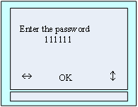
Figure 23 password input
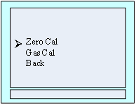
Figure 24 select correction type
Step 2: press the left button to select items zero correction function, and then press right button to enter zero calibration menu, through left button to choose the type of gas as shown in figure 25, then press right button to enter selected gas zero cleaning menu, determine the current gas 0 PPM, press left button to confirm, after the success of the calibration between the bottom of the screen will display success, otherwise display calibration failure, as shown in figure 26.
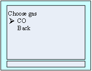
Figure 25 selection of gas type for zero correction
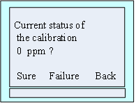
Figure 26 confirm clear
Step 3: Press the right button to return to the interface of gas type selection after the zero correction is completed. At this time, you can choose other gas type to do zero correction. The method is the same as above. After zero clearing, press the menu until to return to the gas detection interface, or automatically exit the menu and return to the gas detection interface after no button pressing is reduced to 0 on the countdown interface.
Gas calibration
Step 1: Turn on the calibration gas. After the displayed value of the gas is stable, enter the main menu and select the calibration selection menu. The specific operation method is Step 1 of zero calibration.
Step 2: Select the function item Gas Calibration, press the right button to enter the calibration gas selection interface, the gas selection method is the same as the zero calibration selection method, after selecting the gas type to be calibrated, press the right button to enter the selected gas calibration value setting interface, As shown in Figure 27, then use the left and right buttons to set the concentration value of the calibration gas. Assuming that the calibration is now carbon monoxide gas, the concentration value of the calibration gas is 500ppm, then set it to '0500'. As shown in Figure 28.
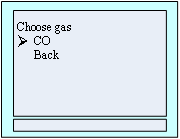
Figure 27 correction gas type selection
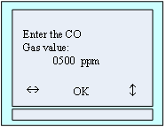
Figure 28 setting the concentration value of standard gas
Step 3: set up after the gas concentration, press the middle button, in the interface to the gas calibration interface, as shown in Figure 29, the interface has a value which is the current detecting gas concentration, when the interface countdown to 10, can press the left button to manual calibration, the gas automatic calibration after 10 s, after a successful interface display XXXX calibration success, otherwise display XXXX calibration failed, Display format is shown in Figure 30.' XXXX 'refers to the calibrated gas type.
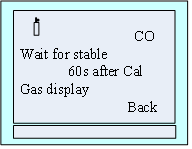
Figure 29 gas calibration
Figure 30 calibration result prompt
Step 4: After the calibration is successful, if the displayed value of the gas is not stable, you can repeat calibration. If the calibration fails, please check whether the concentration of the standard gas is consistent with the calibration setting value. After the gas calibration is completed, press the right button to return to the gas type selection interface to calibrate other gases.
Step 5: After all the gas calibration is completed, press the menu until to return to the gas detection interface, or automatically exit the menu and return to the gas detection interface after the countdown interface reduces to 0 without pressing any button.
3.3.6 Return
In the main menu interface, press the left button to select the 'Return' function, and then press the right button to return to the previous menu.
1. Avoid using the instrument in corrosive environment
2. Be sure to avoid contact between the instrument and water.
3. Do not wire with electricity.
4. Regularly clean the sensor filter to avoid the filter clogging and unable to detect gas normally.
Related products
-
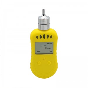
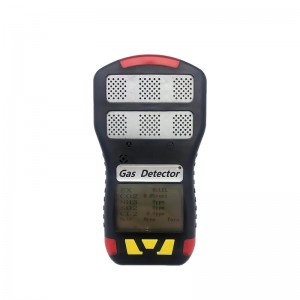
Portable pump suction single gas detector
System Description System configuration 1. Table1 Material List of Portable pump suction single gas detector Gas Detector USB Charger Please check materials immediately after unpacking. The Standard is necessary accessories. The Optional can be chosen according to your needs. If you have no need to calibrate, set the alarm parameters, or read the alarm record, don’t purchase the optional acc...
-
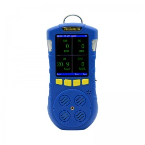
Compound Portable Gas Detector
Product description The composite portable gas detector adopts 2.8-inch TFT color screen display, which can detect up to 4 kinds of gases at the same time. It supports the detection of temperature and humidity. The operation interface is beautiful and elegant; it supports display in both Chinese and English. When the concentration exceeds the limit, the instrument will send out sound, light and vibrat...
-
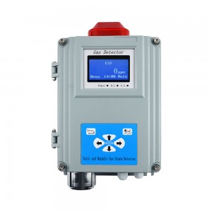
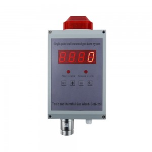
Compound single point wall mounted gas alarm
Product Parameters ● Sensor: Combustible gas is catalytic type, other gases are electrochemical, except special ● Responding time: EX≤15s; O2≤15s; CO≤15s; H2S≤25s ● Work pattern: continuous operation ● Display: LCD display ● Screen Resolition:128*64 ● Alarming mode: Audible & Light Light alarm -- High intensity strobes Audible alarm -- above 90dB ● Output control: relay output with two wa...
-
Single-point Wall-mounted Gas Alarm (Chlorine)
Technical parameter ● Sensor: catalytic combustion ● Responding time: ≤40s (conventional type) ● Work pattern: continuous operation, high and low alarm point(could be set) ● Analog interface: 4-20mA signal output[option] ● Digital interface: RS485-bus interface [option] ● Display mode: Graphic LCD ● Alarming mode: Audible alarm -- above 90dB; Light alarm -- High intensity strobes ● Output control: rel...
-
Portable compound gas detector
System instruction System configuration No. Name Marks 1 portable compound gas detector 2 Charger 3 Qualification 4 User manual Please check whether the accessories are complete immediately after received the product. Standard configuration is a must-have for purchasing equipment. Optional configuration is separately configured according to your needs, if y...
-
Single-point Wall-mounted Gas Alarm
Structure chart Technical parameter ● Sensor: electrochemistry, catalytic combustion, infrared, PID...... ● Responding time: ≤30s ● Display mode: High brightness red digital tube ● Alarming mode: Audible alarm -- above 90dB(10cm) Light alarm --Φ10 red light-emitting diodes (leds) ...


