

China Cheap price Portable Gas Detector - Single-point Wall-mounted Gas Alarm – Huacheng
China Cheap price Portable Gas Detector - Single-point Wall-mounted Gas Alarm – Huacheng Detail:
● Sensor: catalytic combustion
● Responding time: ≤40s (conventional type)
● Work pattern: continuous operation, high and low alarm point(could be set)
● Analog interface: 4-20mA signal output [option]
● Digital interface: RS485-bus interface [option]
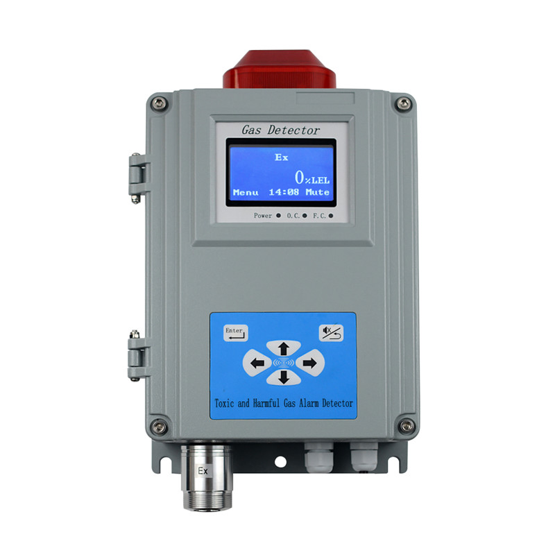
● Display mode: Graphic LCD
● Alarming mode: Audible alarm — above 90dB; Light alarm — High intensity strobes
● Output control: relay output with two way alarming control
● Additional function: time display、calendar display
● Storage: 3000 alarm records
● Working power supply: AC95~265V, 50/60Hz
● Power consumption: <10W
● Water and dusk proof: IP65
● Temperature range:-20℃ ~ 50℃
● Humidity range:10 ~ 90%(RH) No condensation
● Installing mode: wall-mounted installing
● Outline dimension: 335mm×203mm×94mm
● Weight: 3800g
Table 1: Technical parameters of gas-detecting
|
Gas |
Technical Parameters |
||||
|
Alarm point I |
Alarm point II |
Measure range |
Resolution |
Unit |
|
|
F-01 |
F-02 |
F-03 |
F-04 |
F-05 |
|
|
EX |
25 |
50 |
100 |
1 |
%LEL |
|
O2 |
18 |
23 |
30 |
0.1 |
%VOL |
|
CO |
50 |
150 |
2000 |
1 |
ppm |
|
1000 |
1 |
ppm |
|||
|
H2S |
10 |
20 |
200 |
1 |
ppm |
|
H2 |
35 |
70 |
1000 |
1 |
ppm |
|
SO2 |
5 |
10 |
100 |
1 |
ppm |
|
NH3 |
35 |
70 |
200 |
1 |
ppm |
|
NO |
10 |
20 |
250 |
1 |
ppm |
|
NO2 |
5 |
10 |
20 |
1 |
ppm |
|
CL2 |
2 |
4 |
20 |
1 |
ppm |
|
O3 |
2 |
4 |
50 |
1 |
ppm |
|
PH3 |
5 |
10 |
100/1000 |
1 |
PPM |
|
1 |
2 |
20 |
1 |
ppm |
|
|
ETO |
10 |
20 |
100 |
1 |
ppm |
|
HCHO |
5 |
10 |
100 |
1 |
ppm |
|
VOC |
10 |
20 |
100 |
1 |
ppm |
|
C6H6 |
5 |
10 |
100 |
1 |
ppm |
|
CO2 |
2000 |
5000 |
50000 |
1 |
ppm |
|
0.2 |
0.5 |
5 |
0.01 |
VOL |
|
|
HCL |
10 |
20 |
100 |
1 |
ppm |
|
HF |
5 |
10 |
50 |
1 |
ppm |
|
N2 |
82 |
90 |
70-100 |
0.1 |
%VOL |
ALA1 Low alarm
ALA2 High alarm
Prev Previous
Set Para Parameter settings
Com Set Communication settings
Num Number
Cal Calibration
Addr Address
Ver Version
Min Minutes
1. Wall-mounted detecting alarm one
2. 4-20mA output module (option)
3. RS485 output (option)
4. Certificate one
5. Manual one
6. Installing component one
6.1 device installing
Installing dimension of device is shown in Figure 1.Firstly, punch at the proper height of wall, install expanding bolt, then fix it up.

Figure 1: installing dimension
6.2 Output wire of relay
When gas concentration exceeds the alarming threshold, the relay in the device will switch on/off, and users could connect linkage device such as fan. The reference picture is shown in Figure 2.
Dry contact is used in the inside battery and device need to be connected in the outside, pay attention to the safe use of electricity and be careful of electric shock.
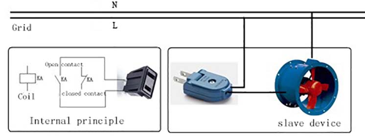
Figure 2: wiring reference picture of relay
Provides two relay outputs, one is normally open and another is normally closed. Figure 2 is a schematic view of the normally open.
6.3 4-20mA output wiring [option]
Wall-mounted gas detector and control cabinet (or DCS) connect via 4-20mA Current signal. The interface shown in Figure 4:
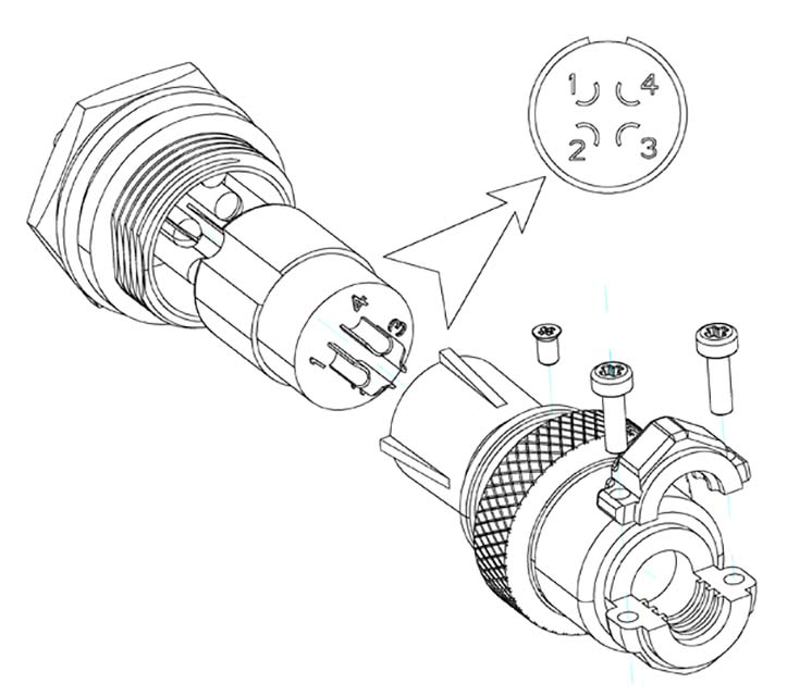
Figure3: Aviation plug
The 4-20mA wiring corresponding shown in Table2:
Table 2: 4-20mA wiring corresponding table
|
Number |
Function |
|
1 |
4-20mA signal output |
|
2 |
GND |
|
3 |
None |
|
4 |
None |
The 4-20mA connection diagram shown in Figure 4:

Figure 4: 4-20mA connection diagram
The flow path of connecting leads is as follows:
1. Pull the aviation plug off the shell, unscrew the screw, get out the inner core marked “1, 2, 3, 4″.
2. Put 2-core shielding cable through the outer skin, then according to Table 2 terminal definition welding wire and conductive terminals.
3. Install the components to the original place, tighten all the screws.
4. Put the plug in the socket, and then tighten it.
Notice:
As to the processing method of shielding layer of cable, please execute a single end connection, connect shielding layer of controller end with the shell In order to avoid interference.
6.4 RS485 connecting leads [option]
The instrument can connect controller or DCS through the RS485 bus. Connection method similar 4-20mA, please refer 4-20mA wiring diagram.
The instrument has 6 buttons, a liquid crystal display, alarm device (alarm lamp, a buzzer) could be calibrated, set the alarm parameters and read alarm record. The instrument has memory function, and it can record the state and time alarm timely. The specific operation and functional are shown below.
7.1 Equipment description
When the device is powered on, it will enter the display interface. The process is shown in Figure 5.
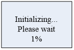
Figure 5: Boot display interface
The function of device initialization is that when the parameter of device is stable, it will preheat the sensor of instrument. X% is currently running time, the running time will vary according to the type of sensors.
As what shows in Figure 6:
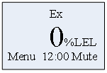
Figure 6: Display interface
The first line shows the detecting name, the concentration values is shown in the middle, the unit is shown on the right, year ,date and time will be shown circularly.
When alarming occurs,  will be shown on the upper right corner, the buzzer will buzz, the alarm will twinkle, and relay respond according to the settings; If you press the mute button, the icon will become
 , the buzzer will be silent, no alarm icon is not displayed.
Every half an hour, it saves the current concentration values. When the state of alarm changes, it records it. For example, it changes from normal to level one, from level one to level two or level two to normal. If it keeps alarming, recording will not be occurred.
7.2 Function of buttons
Button functions are shown in Table 3.
Table 3: Function of buttons
|
Button |
Function |
 |
Display the interface timely and Press the button in the menu Enter the child menu Determine the set value |
 |
Mute Back to the former menu |
 |
Selection menuChange the parameters |
 |
Selection menu Change the parameters |
 |
Select the setting value column Decrease the setting value Change the setting value. |
 |
Select the setting value column Change the setting value. Increase the setting value |
7.3 Check parameters
If there is a need to see the gas parameters and recording data, you could anyone of the four arrow buttons to enter the parameter-checking interface on the concentration display interface.
For example, press to see the interface below. As shows in Figure 7:
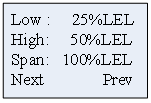
Figure 7: Gas parameters
Press to enter the memory interface (Figure 8), press to enter specific alarming recording interface (Figure 9), press back to detecting display interface.
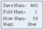
Figure 8: memory state
Save Num: The total number of records for the storage.
Fold Num: When the written record is full, it will start from the first cover storage, and coverage counts will add 1.
Now Num: The index of Currently storage
Press or to the next page, alarming records are in the Figure 9
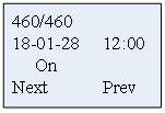
Figure 9: boot record
Display from the last records.
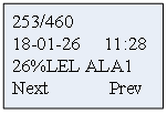
Figure 10: alarm record
Press or to the next page, press back to the detecting display interface.
Notes: when checking parameters, not pressing any keys for 15s, the instrument will automatically return to the detection and display interface.
7.4 Menu operation
When in the real-time concentration display interface, press to enter the menu. The menu interface are shown in Figure 11, press or to choose any function interface, press to enter this function interface.
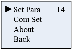
Figure 11: Main menu
Function description:
Set Para: Time settings, alarm value settings, device calibration and switch mode.
Com Set: Communication parameters settings.
About: The version of device.
Back: Back to the gas-detecting interface.
The number on the upper right is the countdown time, when there is no key operation 15 seconds later, will exit the menu.
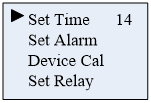
Figure 12: System setting menu
Function description:
Set Time: Time settings, including year, month, day, hours and minutes
Set Alarm: Set alarm value
Device Cal: Device calibration, including zero point correction, correction of calibration gas
Set Relay: Set relay output
7.4.1 Set Time
Select “Set Time”, press to enter. As Figure 13 shows:
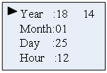
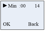
Figure 13: Time setting menu
Icon  is referring to the currently selected to adjust the time, press or to change data. After selecting data, press orto choose to regulate other time functions.
Function description:
● Year set range 18 ~ 28
● Month set range 1~12
● Day set range 1~31
● Hour set range 00~23
● Minute set range 00 ~ 59.
Press to determine the setting data, Press to cancel, back to former level.
7.4.2 Set Alarm
Select “Set Alarm”, press to enter. The following combustible gas devices to be an example. As shown in figure 14:
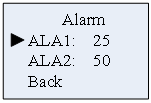
Figure 14: Combustible gas alarm value
Choose Low alarm value is set, and then press to enter the Settings menu.
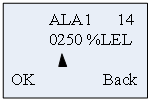
Figure 15: Set the alarm value
As shown in figure 15, press orto Switch data bits, press orto increase or decrease data.
After the completion of the set, press, confirm numerical interface into the alarm value, press to confirm, after the success of the Settings below ‘success’, whereas tip ‘failure’, as shown in figure 16.
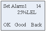
Figure 16: Settings success interface
Note: set the alarm value must be smaller than the factory values (oxygen lower limit alarm value must be greater than the factory setting); otherwise, it will be set a failure.
After level set is finished, it returns to the alarm value set type selection interface as shown in figure 14, the secondary alarm operation method is same as above.
7.4.3 Equipment calibration
Note: powered on, initialize the rear end of zero calibration, calibration gas, correction must be corrected when zero air calibration again.
Parameter Settings – > calibration equipment, enter the password: 111111
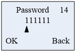
Figure 17: Input password menu
Correct password into the calibration interface.
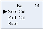
Figure 18: Calibration option
● Zero calibration
Pass into the standard gas(No oxygen), choose ‘Zero Cal’ function, then press into the zero calibration interface. After determining the current gas after 0 %LEL, press to confirm, below middle will display ‘Good’ vice display ‘Fail’ .As shown in figure 19.
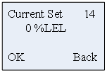
Figure 19: Select zero
After the completion of the zero calibration, press back to the calibration interface. At this time, gas calibration can be chosen, or return to the interface of test gas level by level, or in a countdown interface, when any button does not be pressed and time reduces to 0,it automatically exit menu to return to the gas detection interface.
● Gas calibration
If gas calibration is needed, this needs to operate under the environment of a standard gas.
Pass into the standard gas, choose ‘Full Cal’ function, press to enter the gas density Settings interface, through or or set the density of the gas, assuming that the calibration is methane gas, the gas density is 60, at this time, please set to’ 0060 ‘. As shown in figure 20.
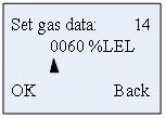
Figure 20: Confirmation interface
After setting the standard gas density, press, into the calibration gas interface, as shown in figure 21:
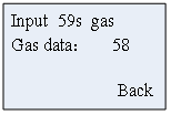
Figure 21: Gas calibration
Display the current detecting gas concentration values, pipe in standard gas. As the countdown gets to 10, press to calibrate manually. Or after 10s, gas automatically calibrates. After a successful interface, it displays ‘Good ’and vice, display ’Fail ’.
● Relay Set:
Relay output mode, type can be selected for always or pulse, just as what shows in Figure22:
Always: when alarming occurs, relay will keep actuating.
Pulse: when alarming occurs, relay will actuate and after the Pulse time, the relay will be disconnected.
Set according to the connected equipment.
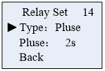
Figure 22: Switch mode selection
Note: The default setting is Always mode output
7.4.4 Communication settings:
Set relevant parameters about RS485
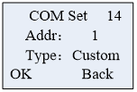
Figure 23: Communication settings
Addr: address of slave devices, range: 1-255
Type: read only, Custom (non-standard) and Modbus RTU, the agreement can not be set.
If RS485 is not equipped, this setting will not work.
7.4.5 About
Version information of display device is shown in Figure 24
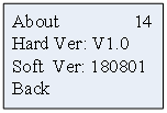
Figure 24: Version Information
The warranty period of the gas detection instrument produced by my company is 12 months and warranty period is valid from the date of delivery. Users shall comply with the instructions. Due to the improper use, or poor working conditions, the instrument damage caused is not in the scope of the warranty.
1. Before using the instrument, please read the instructions carefully.
2. The use of the instrument must be in accordance with the rules set in the manual operation.
3. The instrument maintenance and replacement of parts should be processed by our company or around the pit.
4. If the user is not in accordance with the above instructions to boot repair or replacement parts, the reliability of the instrument shall be the responsibility of the operator.
5. The use of the instrument should also abide by the relevant domestic departments and factory equipment management laws and rules.
Product detail pictures:


Related Product Guide:
We always get the job done being a tangible workforce making sure that we can easily give you the very best quality as well as finest selling price for China Cheap price Portable Gas Detector - Single-point Wall-mounted Gas Alarm – Huacheng , The product will supply to all over the world, such as: Mauritius, Lithuania, Lebanon, Our company insists on the purpose of "takes service priority for standard, quality guarantee for the brand, do business in good faith, to offer skilled, rapid, accurate and timely service for you". We welcome old and new customers to negotiate with us. We are going to serve you with all sincerity!
We have been looking for a professional and responsible supplier, and now we find it.
Related products
-
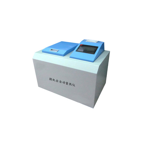
Hot Selling for Clear Pipette - Microcomputer ...
Microcomputer automatic calorimeter is suitable for electric power, coal, metallurgy, petrochemical, environmental protection, cement, papermaking, ground can, scientific research institutions and other industrial sectors to measure the calorific value of coal, coke and petroleum and other combustible materials. In line with GB/T213-2008 “Coal thermal determination Method” GB/T384 “Determination of calorific value of petroleum products” JC/T1005-2006 “Cement blac...
-
Professional Design Digital Micro Pipette - Mi...
Microcomputer automatic calorimeter is suitable for electric power, coal, metallurgy, petrochemical, environmental protection, cement, papermaking, ground can, scientific research institutions and other industrial sectors to measure the calorific value of coal, coke and petroleum and other combustible materials. In line with GB/T213-2008 “Coal thermal determination Method” GB/T384 “Determination of calorific value of petroleum products” JC/T1005-2006 “Cement blac...
-
Best Price on Measures Air Temperature - Micr...
Microcomputer automatic calorimeter is suitable for electric power, coal, metallurgy, petrochemical, environmental protection, cement, papermaking, ground can, scientific research institutions and other industrial sectors to measure the calorific value of coal, coke and petroleum and other combustible materials. In line with GB/T213-2008 “Coal thermal determination Method” GB/T384 “Determination of calorific value of petroleum products” JC/T1005-2006 “Cement blac...
-
Factory source Sample Cup - Microcomputer auto...
Microcomputer automatic calorimeter is suitable for electric power, coal, metallurgy, petrochemical, environmental protection, cement, papermaking, ground can, scientific research institutions and other industrial sectors to measure the calorific value of coal, coke and petroleum and other combustible materials. In line with GB/T213-2008 “Coal thermal determination Method” GB/T384 “Determination of calorific value of petroleum products” JC/T1005-2006 “Cement blac...
-
Factory Supply Ultrasonic Multiparameter Sensor...
Water-carrying caliber Ф200 ± 0.6mm Measuring range ≤4mm / min (precipitation intensity) Resolution 0.2mm (6.28ml) Accuracy ± 4% (indoor static test, rain intensity is 2mm / min) Power supply mode DC 5V DC 12V DC 24V Other Output form Current 4 ~ 20mA Switching signal: On-off of reed switch Voltage: 0~2.5V Voltage: 0~5V Voltage 1 ~ 5V Other Instrument line length Standard: 5 meters Other Working temperature 0 ~ 50 ℃ Storage temperature -10 ℃ ~ ...
-
Professional China Noise Meter - Laboratory p...


