

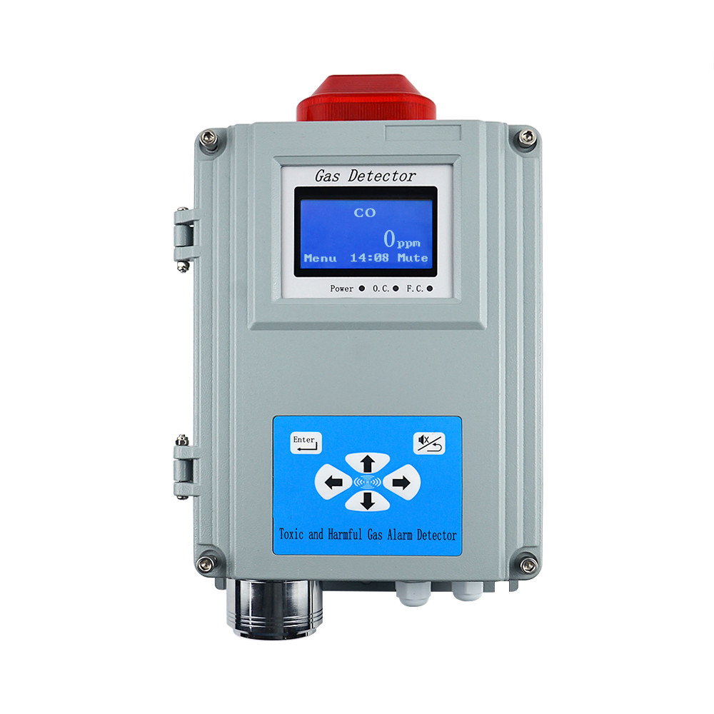
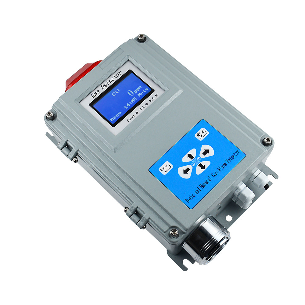
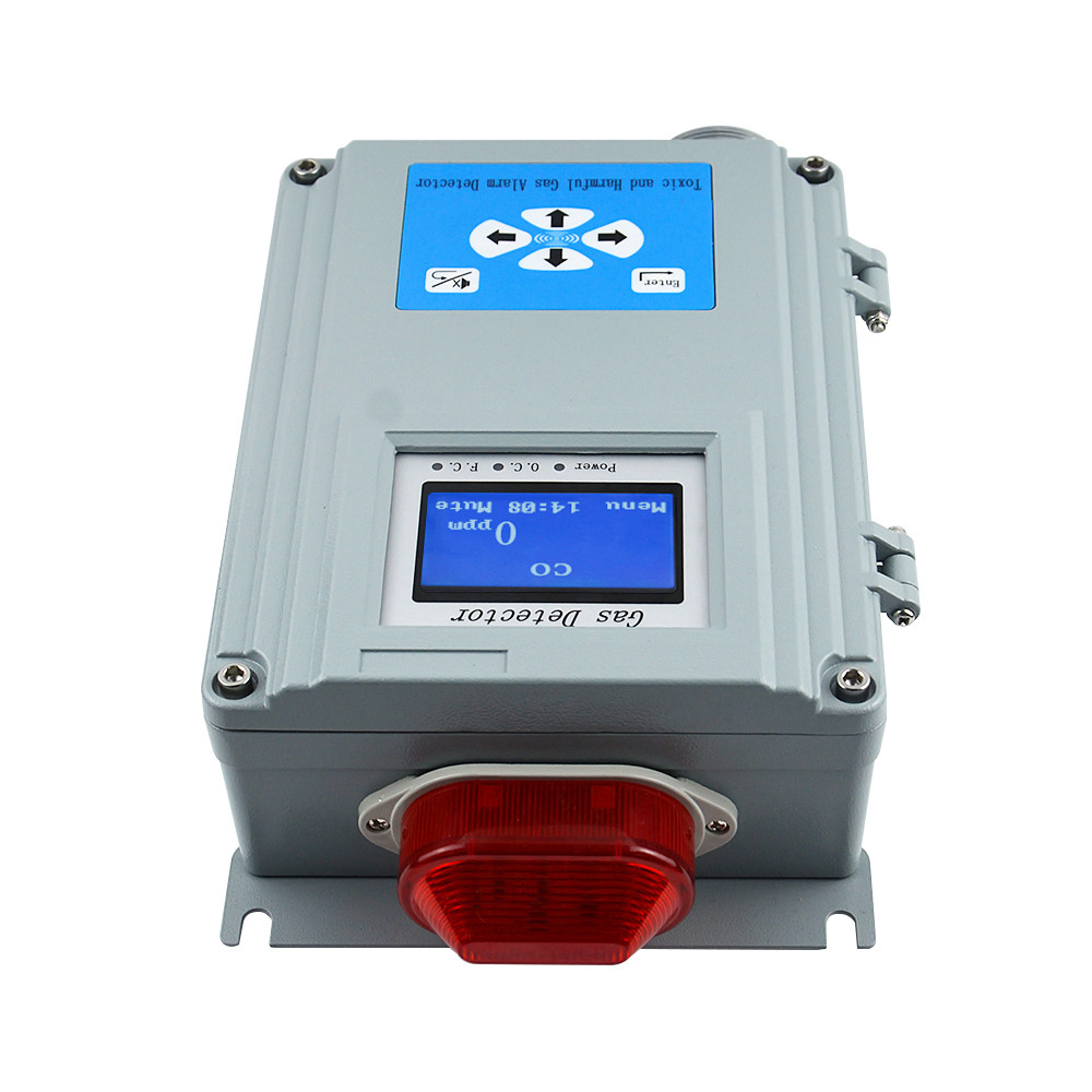
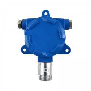
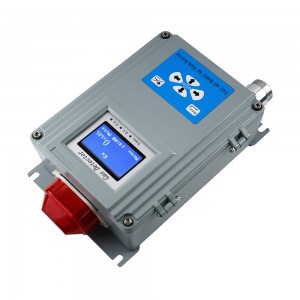
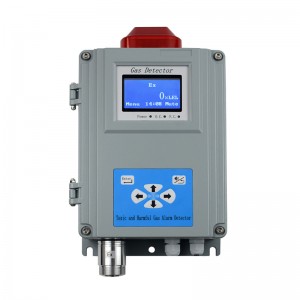
Compound single point wall mounted gas alarm


● Sensor: Combustible gas is catalytic type, other gases are electrochemical, except special
● Responding time: EX≤15s; O2≤15s; CO≤15s; H2S≤25s
● Work pattern: continuous operation
● Display: LCD display
● Screen Resolition:128*64
● Alarming mode: Audible & Light
Light alarm -- High intensity strobes
Audible alarm -- above 90dB
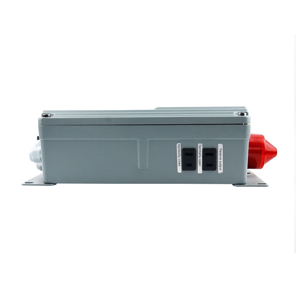
● Output control: relay output with two way(normally open, normally closed)
● Storage: 3000 alarm records
● Digital interface: RS485 output interface Modbus RTU (optional)
● Backup power supply: provide power outage for more than 12 hours (optional)
● Working power supply: AC220V, 50Hz
● Temperature range:-20℃ ~ 50℃
● Humidity range:10 ~ 90% (RH) No condensation
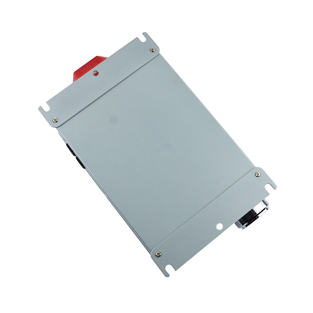
● Installing mode: wall-mounted installing
● Outline dimension: 203mm×334mm×94mm
● Weight: 3800g
Technical parameters of gas-detecting
Table 1 Technical parameters of gas-detecting
|
Gas |
Gas Name |
Technical index |
|||
|
Measure Range |
Resolution |
Alarm Point |
|||
|
CO |
Carbon monoxide |
0-1000ppm |
1ppm |
50ppm |
|
|
H2S |
Hydrogen sulfide |
0-200ppm |
1ppm |
10ppm |
|
|
H2 |
Hydrogen |
0-1000ppm |
1ppm |
35ppm |
|
|
SO2 |
Sulfur dioxide |
0-100ppm |
1ppm |
5ppm |
|
|
NH3 |
Ammonia |
0-200ppm |
1ppm |
35ppm |
|
|
NO |
Nitric oxide |
0-250ppm |
1ppm |
25ppm |
|
|
NO2 |
Nitrogen dioxide |
0-20ppm |
1ppm |
5ppm |
|
|
CL2 |
Chlorine |
0-20ppm |
1ppm |
2ppm |
|
|
O3 |
Ozone |
0-50ppm |
1ppm |
5ppm |
|
|
PH3 |
Phosphine |
0-1000ppm |
1ppm |
5ppm |
|
|
HCL |
Hydrogen chloride |
0-100ppm |
1ppm |
10ppm |
|
|
HF |
Hydrogen fluoride |
0-10ppm |
0.1ppm |
1ppm |
|
|
ETO |
Ethylene Oxide |
0-100ppm |
1ppm |
10ppm |
|
|
O2 |
Oxygen |
0-30%vol |
0.1%vol |
High 18%vol Low 23%vol |
|
|
CH4 |
CH4 |
0-100%LEL |
1%LEL |
25%LEL |
|
Note: this instrument is for reference only.
Only specified gases can be detected. For more gas types, please call us.
Table 2 Product List
|
No. |
Name |
Quantity |
|
|
1 |
Wall Mounted Gas Detector |
1 |
|
|
2 |
RS485 output module |
1 |
Option |
|
3 |
Backup battery and charging kit |
1 |
Option |
|
4 |
Certificate |
1 |
|
|
5 |
Manual |
1 |
|
|
6 |
Installing component |
1 |
Device Installing
Installing dimension of device is shown in Figure 1.Firstly, punch at the proper height of wall, install expanding bolt, then fix it up.
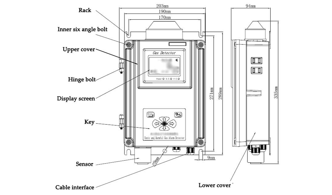
Figure 1: Device Construction
Output wire of relay
When gas concentration exceeds the alarming threshold, the relay in the device will switch on/off, and users could connect linkage device such as fan. The reference picture is shown in Figure 2.Dry contact is used in the inside battery and device need to be connected in the outside, pay attention to the safe use of electricity and be careful of electric shock.

Figure 2: Wiring reference picture of relay
RS485 Connection
The instrument can connect controller or DCS through the RS485 bus.
Note: RS485 output interface mode is subject to the actual.
1. Regarding the treatment method of shield layer of shielded cable, please perform single-end connection. It is recommended that the shield layer at one end of the controller be connected to the shell to avoid interference.
2. If the device is far away, or if multiple devices are connected to the 485 bus at the same time, it is recommended to install a 120-euro terminal resistor on the terminal device.
The instrument has 6 buttons, an LCD screen, related alarm devices (alarm lights, buzzer) can be calibrated, set alarm parameters and read alarm records. The instrument itself has a storage function, which can record the alarm status and time in real time. For specific operations and functions, please see the description below.
Instrument working instruction
After the instrument is powered on, enter the boot display interface, displaying the product name and version number. As shown in Figure 3:
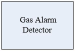
Figure 3: Boot display interface
Then show the initialization interface, as shown in figure 4:
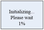
Figure 4: initialization interface
The function of initialization is to wait for the instrument parameters to stabilize and warm up the sensor. X% is the currently running progress.
After the sensor warms up, the instrument enters the gas detection display interface. The values of multiple gases are displayed cyclically, as shown in Figure 5:
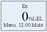
Figure 5: Concentration display interface
The first line displays the detected gas name, the concentration value is in the middle, unit is on the right, and the year, date, and time are displayed cyclically below.
When any gas alarm occurs, the upper right corner displays , the buzzer sounds, the alarm light flashes, and the relay acts according to the setting; if the mute button is pressed, the icon changes as, the buzzer mute; no alarm, icon is not displayed.
Every half hour, store the current concentration of all gases. The alarm status changes and is recorded once, for example from normal to first level, first level to second level or second level to normal. If it keeps alarming, it will not be stored.
Button function
Button functions are shown in table 3:
Table 3 Button function
| Button | Function |
 |
l Press this button to enter the menu in the real-time display interface l Enter sub-menu l Determine the setting value |
 |
l Silence, press this button to silence when an alarm occurs l Return to previous menu |
 |
l Select menu l Change the setting value |
 |
Select menu Change the setting value |
 |
Select setting value column Decrease setting value Change the setting value |
 |
Select setting value column Increase the setting value Change the setting value |
View parameter
If there is a need to view gas parameters and store recorded data, in the real-time concentration display interface, you can press any button in the up, down, left, right, to enter the parameter view interface.
Example, press button  to check show in figure 6
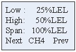
Figure 6: Gas parameter
Press button to show other gas parameters, after all gas parameters are displayed, press button to enter the storage state view interface as shown in figure 7
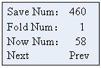
Figure 7: Storage state
Total storage: the total number of records currently stored.
Overwrite times: when the memory of the written record is full, the store is over written from the first, and the overwrite times are increased by 1.
Current sequence number: the physical sequence number of the storage.
Press button to enter the specific alarm record as shown in figure 8, press button return to the detection display screen.
Press button  or to enter next page, alarm records are shown in figure 8 and figure 9.
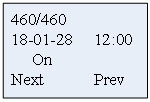
Figure 8: Boot record
Show from the last record
Press button  or
or  to previous page, press button exit to the detection display screen
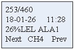
Figure 9: Alarm records
Note: If does not press any button during 15s when viewing the parameters, the instrument will automatically return to the detection display interface。
If you need to clear the alarm records, enter the menu parameter settings-> device calibration password input interface, enter 201205 and press OK, all alarm records will be cleared.
Menu operation instructions
On the real-time concentration display interface, press button  to enter the menu. The main interface of the menu is shown in Figure 10. Press button or to select the function and press button to enter the function.
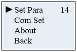
Figure 10: Main menu
Function description
● Set Para: time setting, alarm value setting, instrument calibration and switch mode.
● Communication setting: communication parameter setting.
● About: device version information.
● Back: return to the gas detection interface.
The number on the upper right is the countdown time. If there is no button operation during 15 seconds, the countdown will exit to the concentration value display interface.
If you want to set some parameters or calibration, please select "parameter setting" and press button to enter the function, as shown in figure 11:
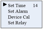
Figure 11: System Setting Menu
Function description
● Time setting: set the current time, you can set the year, month, day, hour, minute
● Alarm setting: set the device alarm value, the first level (lower limit) alarm value and the second level (upper limit) alarm value
● Calibration: zero point calibration and instrument calibration (please operate with standard gas)
● Switch mode: set relay output mode
Time setting
Select "Time Setting" and press button enter. Figures 12 and 13 show the time setting menu.
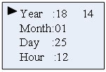
Figure 12: Time setting menu I
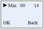
Figure 13: Time setting menu II
The icon  refers to the currently selected time to be adjusted. Press button or to change the data. After selecting the desired data, press button or to select other time functions.
Function description
● Year: the setting range is 20 ~ 30.
● Month : the setting range is 01 ~ 12.
● Day: the setting range is 01 ~ 31.
● Hour: the setting range is 00 ~ 23.
● Minute: the setting range is 00 ~ 59.
Press button to confirm the setting data, press button to cancel the operation and return to the previous level.
Alarm setting
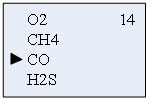
Select "Alarm setting", Press button to enter and select the gas which needs to be setting, show as figure 14.

Figure14: Gas selection interface
Example, select CH4, press button to show the parameters of CH4, show as figure 15.
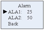
Figure 15: Carbon monoxide alarm setting
Select "the first level alarm", press button to enter the setting menu, show as figure 16.
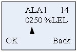
Figure 16: The first level alarm setting
At this time, press button or to switch the data bit, press button or to increase or decrease the value, after setting, press button to enter the alarm value confirmation value interface, press button to confirm, after the setting is successful, the bottom shows "success", otherwise it prompts "failure", as shown in Figure 17 Show.
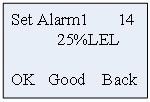
Figure 17: Setting success interface
Note: The set alarm value must be less than the factory value (the oxygen lower limit alarm must be greater than the factory setting value) otherwise it will fail to set.
After the first level setting is completed, press button to the alarm value setting selection interface as shown in Figure 15. The operation method for setting the second level alarm is the same as above. After the setting is completed, press the return button to return to the gas type selection interface, you can select the gas to set, if you do not need to set other gases, press button until return to the real-time concentration display interface.
Equipment calibration
Note: powered on, zero calibration and gas calibration can be performed after initialization, and zero calibration must be performed before calibration
Parameter Settings - > calibration equipment, enter the password: 111111

Figure 18: Input password menu
Press and Correct password into the calibration interface as figure 19.
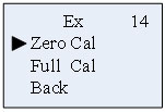
Figure 19: Calibration option
Select calibration type and press enter to gas type selection, select the calibrated gas, as figure 20, press enter to calibration interface.
Select gas type interface
Take CO gas as an example below:
Zero calibration
Pass into the standard gas(No oxygen), choose 'Zero Cal' function, then press into the zero calibration interface. After determining the current gas after 0 ppm, press to confirm, below middle will display 'Good' vice display 'Fail'. As shown in figure 21.
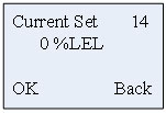
Figure 21: Select zero
After the completion of the zero calibration, press back to the calibration interface. At this time, gas calibration can be chosen, or return to the test gas interface level by level, or in a countdown interface, without pressing any buttons and time reduces to 0,it automatically exit menu to return to the gas detection interface.
Gas calibration
If gas calibration is needed, this needs to operate under the environment of a standard gas.
Pass into the standard gas, choose 'Full Cal' function, press to enter the gas density Settings interface, through or or set the density of the gas, assuming that the calibration is methane gas, the gas density is 60, at this time, please set to' 0060 '. As shown in figure 22.
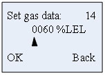
Figure 22: Set the standard of gas density
After setting the standard gas density, press into the calibration gas interface, as shown in figure 23:
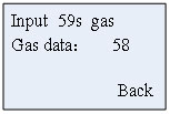
Figure 23: Gas calibration
Display the current detecting gas concentration values, pass into standard gas. As the countdown gets to 10S, press to calibrate manually. Or after 10s, gas automatically calibrated. After a successful interface, it displays 'Good 'or display 'Fail '.As figure 24.

Figure 24: Calibration result
Relay Set:
Relay output mode, type can be selected for always or pulse, just as what shows in Figure 25:
Always: when alarming occurs, relay will keep actuating.
Pulse: when alarming occurs, relay will actuate and after the Pulse time, the relay will be disconnected.
Set according to the connected equipment.
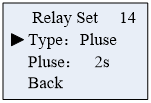
Figure 25: Switch mode selection
Communication settings
Set relevant parameters as figure 26.
Addr: address of slave devices, range: 1-99
Type: read only, non-standard or Modbus RTU, the agreement cannot be set.
If RS485 is not equipped, this setting will not work.
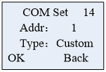
Figure 26: Communication settings
About
Version information of display device is shown in Figure 27
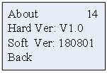
Figure 27: Version Information
Table 4 Common malfunctions and solutions
|
Malfunctions |
Cause |
Resolution |
| After turning on the power supply gas sensor cannot connected | Connection failure between sensor board and host | Open the panel to check whether it connected well. |
| Alarm value setting failed | Alarm value set must be less than or equal to factory value, except for oxygen | Check whether the alarm value is greater than the factory setting value. |
| Zero correction failure | Current concentrations is too high ,is not allowed | It can be operated with pure nitrogen or in clean air. |
| No change when input standard gas | Sensor expiration | Contact after sell service |
| Oxygen gas detector but display 0%VOL | Sensor failure or expiration | Contact after sell service |
| For Ethylene oxide, hydrogen chloride detector, it has been display full range after the boot | For such sensors to warm up it needs powered off and recharged,after 8-12 hours warm up it will works normally | Wait until the sensors warm up finished |
Related products
-
Bus transmitter Instructions
485 Overview 485 is a kind of serial bus which is widely used in industrial communication. 485 communication only needs two wires (line A, line B), long distance transmission is recommended to use shielded twisted pair. Theoretically, the maximum transmission distance of 485 is 4000 feet and the maximum transmission rate is 10Mb/s. The length of the balanced twisted pair is inversely proportional to t...
-
Single-point Wall-mounted Gas Alarm (Chlorine)
Technical parameter ● Sensor: catalytic combustion ● Responding time: ≤40s (conventional type) ● Work pattern: continuous operation, high and low alarm point(could be set) ● Analog interface: 4-20mA signal output[option] ● Digital interface: RS485-bus interface [option] ● Display mode: Graphic LCD ● Alarming mode: Audible alarm -- above 90dB; Light alarm -- High intensity strobes ● Output control: rel...
-
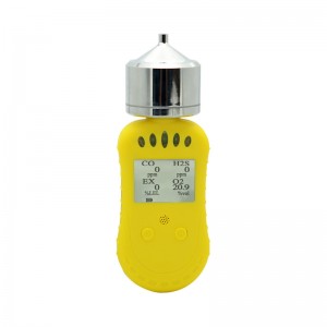
Composite portable gas detector
System Description System configuration 1. Table1 Material List of Composite portable gas detector Portable pump composite gas detector USB Charger Certification Instruction Please check materials immediately after unpacking. The Standard is necessary accessories. The Optional is can be choose according to your needs. If you have no need to calibration, set the alarm parameters, or rea...
-
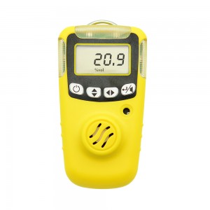
Single Gas Detector User’s
Prompt For security reasons, the device only by suitably qualified personnel operation and maintenance. Prior to the operation or maintenance, please read and fully manage all solutions to these instructions. Including operations, maintenance of equipment and process methods. And a very important safety precautions. Read the following Cautions before using the detector. Table 1 Cautions Cautions ...
-
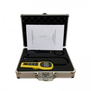
Portable combustible gas leak detector
Product Parameters ● Sensor Type: Catalytic sensor ● Detect gas: CH4/Natural gas/H2/ethyl alcohol ● Measure range: 0-100%lel or 0-10000ppm ● Alarm point: 25%lel or 2000ppm ,adjustable ● Accuracy: ≤5%F.S ● Alarm: Voice + vibration ● Language: Support English& Chinese menu switch ● Display: LCD digital display, Shell Material: ABS ● Working voltage: 3.7V ● Battery capacity: 2500mAh Lithium battery ●...
-
Single-point Wall-mounted Gas Alarm
Technical parameter ● Sensor: catalytic combustion ● Responding time: ≤40s (conventional type) ● Work pattern: continuous operation, high and low alarm point(could be set) ● Analog interface: 4-20mA signal output [option] ● Digital interface: RS485-bus interface [option] ● Display mode: Graphic LCD ● Alarming mode: Audible alarm -- above 90dB; Light alarm -- High intensity strobes ● Output control: re...


